Are You Making These 5 Critical DFAM Mistakes That Ruin Your 3D Prints?
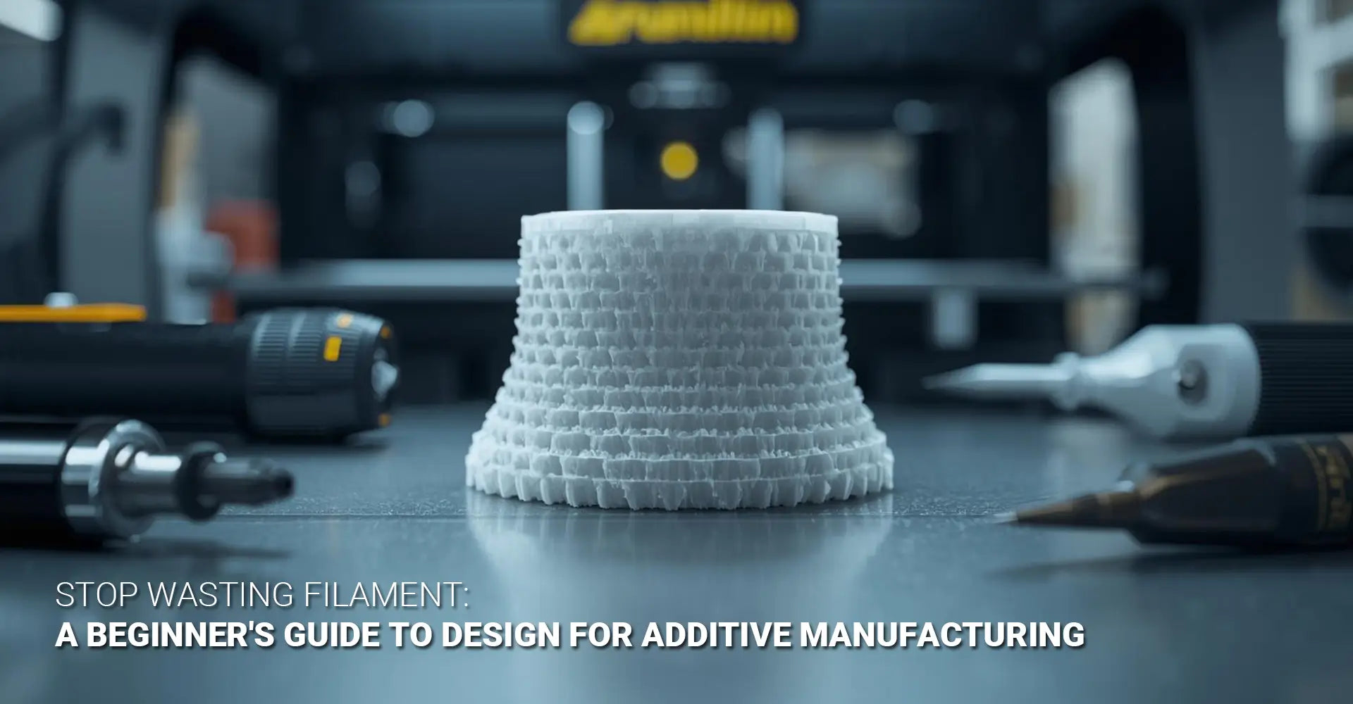
Are You Making These 5 Critical DFAM Mistakes That Ruin Your 3D Prints?

The Hidden Cost of Ignoring DFAM Principles
Every day, designers send CAD files to 3D printers expecting perfect results, only to face warped parts, broken features, and wasted materials. The problem isn't the printer or the filament. Instead, it's that traditional design approaches simply don't translate to additive manufacturing. Consequently, small oversights in the design phase lead to massive frustration, wasted time, and expensive failed prints. Therefore, understanding Design for Additive Manufacturing (DFAM) principles is essential for anyone serious about 3D printing success.
Quick Answer: The 5 Most Common DFAM Mistakes
Here's what's probably going wrong with your prints:
- Ignoring overhang angles and support requirements - Designs with steep overhangs fail without proper support planning
- Using incorrect wall thickness for your material - Too-thin walls crack; inconsistent thickness creates weak points
- Choosing the wrong print orientation - Poor orientation weakens parts by 3-5x and ruins surface quality
- Directly converting injection-molded designs without redesign - Traditional CAD models carry unnecessary constraints
- Failing to account for material-specific constraints - FDM, SLA, and SLS each have unique design rules
Each mistake has a straightforward fix that dramatically improves print success rates. Moreover, applying these corrections will save you hours of troubleshooting and hundreds of dollars in wasted materials.
Why This Guide Matters for Your Next Print
This comprehensive guide walks through each DFAM design for additive manufacturing mistake in detail, showing exactly what goes wrong and how to correct it. Whether you're prototyping for electronics manufacturing, creating components for industrial machinery, or exploring rapid prototyping solutions, understanding these principles will transform your results. Additionally, we'll cover material-specific considerations for 3D printing plastics and other common materials.
Table of Contents
- Why Do Good Designs Print Badly?
- Mistake #1: Are You Designing Away Your Support Structures?
- Mistake #2: Is Your Wall Thickness Setting You Up for Failure?
- Mistake #3: Could Print Orientation Save Your Part from Breaking?
- Mistake #4: Should You Redesign Instead of Direct-Convert Your CAD Files?
- Mistake #5: Are You Ignoring Material-Specific Design Rules?
- Conclusion: Your DFAM Success Checklist
Why Do Good Designs Print Badly?
Many engineers find themselves confused when their perfectly dimensioned CAD models fail during printing. After all, the design looks flawless on screen and passes all traditional engineering checks. However, the disconnect between conventional design and additive manufacturing creates this frustrating gap.
Key Insight: Traditional manufacturing designs prioritize tooling access and material removal. In contrast, additive manufacturing builds layer by layer, which creates completely different structural constraints and opportunities. Therefore, what works for CNC machining or injection molding often fails spectacularly in 3D printing.
The DFAM learning curve exists because additive processes introduce unique physical challenges. First, gravity constantly pulls on unsupported material during printing. Second, each layer must bond properly to the previous one, creating potential weak points. Third, thermal expansion and contraction cause warping if not managed correctly. Furthermore, different materials behave dramatically differently under these conditions.
This means designers must "unlearn" certain CAD habits developed for traditional manufacturing. For instance, thick uniform walls that work well for injection molding add unnecessary weight and print time to 3D printed parts. Similarly, complex internal geometries that would be impossible to machine become simple to print. Therefore, embracing this paradigm shift unlocks additive manufacturing's full potential while avoiding costly mistakes.
Mistake #1: Are You Designing Away Your Support Structures?
Support structures represent one of the most universally frustrating aspects of 3D printing design mistakes. These temporary scaffolds hold up overhanging features during printing, but they come with serious drawbacks. Specifically, supports increase print time by 20-50%, waste expensive material, and leave rough surface finishes that require extensive post-processing.
The 45-Degree Rule: Most FDM printers can successfully print overhangs up to 45 degrees without any supports. However, angles steeper than this require external support structures, which means more cleanup work and rougher surfaces on those faces. Therefore, smart designers work within this constraint whenever possible.
Understanding support structure optimization starts with recognizing which geometries are self-supporting. For example, adding a 45-degree chamfer to a vertical wall eliminates the need for supports entirely. Likewise, designing with gradual fillets instead of sharp 90-degree overhangs keeps your part printable without scaffolding.
However, eliminating all supports isn't always the smartest goal. Sometimes, adding minimal supports to non-critical surfaces produces better results than contorting your design into unnatural shapes. For instance, if one face will be hidden in the final assembly, placing supports there preserves the quality of visible surfaces. Additionally, custom breakaway support structures that are designed into the part itself often remove more cleanly than automatically generated supports.
The key strategy involves three steps: First, analyze your design for overhangs exceeding 45 degrees. Second, explore whether reorienting the part or modifying the geometry can eliminate problematic angles. Third, if supports remain necessary, position them strategically on non-critical surfaces where post-processing won't affect function or appearance.
Mistake #2: Is Your Wall Thickness Setting You Up for Failure?
Wall thickness issues cause more failed prints than almost any other single factor. Parts with walls that are too thin either fail to print entirely or produce fragile components that crack during handling. Conversely, inconsistent thickness creates stress concentration points where parts break under load.
Minimum Wall Thickness Guide:
- FDM (PLA/ABS): 1.0 mm minimum
- FDM (TPU/Flexible): 1.5-2.0 mm minimum
- SLA/DLP (Resin): 0.4-0.6 mm minimum
- SLS (Nylon): 0.7-1.0 mm minimum
These numbers represent tested minimums, but maintaining consistency matters even more than hitting exact values. Moreover, these guidelines vary based on your specific printer's capabilities and material brand.

The most common wall thickness mistake involves sudden transitions. Picture a bracket that goes from 5mm thick at the mounting point to 0.8mm thick at a tab. That dramatic change creates a stress concentrator where the part will almost certainly fail under load. Instead, gradual transitions with smooth fillets distribute stress evenly across the geometry.
Additionally, designers often assume that thicker automatically means stronger. While this holds true to a point, excessive thickness adds weight, increases material costs, and extends print time without proportional strength gains. For instance, increasing a wall from 2mm to 4mm might only improve strength by 20% while doubling print time and material usage.
The solution involves analyzing your part's loading conditions and using appropriate thickness accordingly. High-stress areas need robust walls, while low-stress sections can be thinner to save weight and time. Furthermore, maintaining consistent thickness throughout each section prevents weak points. When transitions are necessary, use gradual tapers of at least 3:1 ratio to avoid stress concentrations.
Mistake #3: Could Print Orientation Save Your Part from Breaking?
Print orientation stands as the most powerful yet misunderstood tool in your DFAM guidelines toolkit. The way you orient a part on the build plate simultaneously affects mechanical strength, surface quality, and support requirements. Consequently, choosing the wrong orientation can reduce part strength by 60-80% compared to ideal positioning.
Critical Fact: Layer lines represent the weakest point in FDM prints because layers bond together less strongly than the material itself bonds internally. Parts fail when force is applied perpendicular to these layer lines. Therefore, orienting your part so that primary forces run parallel to layers can increase strength by 3-5x compared to perpendicular orientation.
Understanding the 3D printing orientation guide principles requires thinking about how your part will be used. For example, consider a bracket that mounts to a wall and supports weight hanging below it. If printed vertically with layers running horizontally, the weight pulls perpendicular to the layers, creating a likely failure point. However, rotating the part so layers run vertically means the load runs parallel to the layers, dramatically increasing strength.
This orientation strategy involves trade-offs beyond just strength. First, different orientations require different amounts of support material. Second, the surface facing the build plate typically has the roughest finish. Third, tall narrow orientations risk tipping over during printing, while wide flat orientations maximize build plate usage.
The decision process should follow this sequence: First, identify the primary load direction your part will experience in use. Second, orient the part so this load runs parallel to layer lines whenever possible. Third, evaluate support requirements and adjust if minimal rotation can significantly reduce supports. Fourth, consider which surfaces are most visible and avoid placing them against the build plate. Finally, verify stability by ensuring the part has adequate contact area with the build plate.
Real-world examples illustrate these principles clearly. A phone case printed with layers running around the perimeter provides excellent drop protection because impact forces compress layers together. The same case printed with layers running from front to back would split easily because impacts would peel layers apart. Similarly, gear teeth should have layers running through their length rather than stacked vertically to withstand rotational forces.
Mistake #4: Should You Redesign Instead of Direct-Convert Your CAD Files?
The single most expensive mistake in additive manufacturing involves taking CAD files designed for injection molding or CNC machining and sending them directly to 3D printers. This approach seems efficient but actually wastes enormous potential while creating numerous problems.
Reality Check: CAD models built for traditional manufacturing carry unnecessary weight, require support structures everywhere, and completely ignore additive's geometric freedom. A true design for 3D printing approach means redesigning from scratch rather than simply converting file formats. Furthermore, parts designed specifically for additive manufacturing can be 40-60% lighter while maintaining equal or greater strength.

Traditional manufacturing imposes constraints that simply don't exist in additive processes. For instance, injection molding requires uniform wall thickness, draft angles for mold release, and avoidance of undercuts. CNC machining demands that all features be accessible to cutting tools, preventing complex internal geometries. These constraints become ingrained in how designers think about parts.
However, additive manufacturing flips these constraints entirely. First, wall thickness can vary freely throughout the part to optimize strength-to-weight ratios. Second, undercuts and complex internal channels print just as easily as simple shapes. Third, multiple components can be consolidated into single prints, eliminating assembly steps. Fourth, organic shapes that would be impossible to machine become straightforward to print.
Topology optimization represents one powerful tool for DFAM redesign. This computational approach removes material from low-stress areas while maintaining strength in critical zones. The resulting shapes often look organic or skeletal but deliver remarkable performance. For example, a traditionally designed mounting bracket might weigh 200 grams with uniform 4mm walls. The topology-optimized version could weigh just 80 grams while handling the same loads, simply by removing unnecessary material and using variable wall thickness.
Part consolidation offers another massive opportunity. Consider an assembly with 12 separate components held together by fasteners. Redesigning for additive manufacturing might reduce this to 3 printed parts with integrated joints, eliminating 9 components and all fasteners. This approach reduces assembly time, eliminates potential failure points, and often costs less despite seemingly complex geometry.
Lattice structures and internal features showcase additive's unique capabilities. Traditional manufacturing cannot create honeycomb internal structures or conformal cooling channels. Additive processes handle these effortlessly, enabling designs that are simultaneously lighter and perform better. Therefore, starting your design process with these possibilities in mind produces dramatically better results than trying to adapt traditional designs.
Mistake #5: Are You Ignoring Material-Specific Design Rules?
Each additive manufacturing process and material combination has unique design requirements that significantly impact success rates. Applying additive manufacturing best practices means understanding these differences rather than using one-size-fits-all design rules.
Material-Specific Guidelines:
FDM (Fused Deposition Modeling)
- Primary concern: Layer adhesion and overhang angles
- Minimum feature size: 0.8-1.0mm depending on nozzle
- Critical factors: Print temperature affects warping; heated beds prevent lifting
- Best for: Functional prototypes, jigs, fixtures
SLA/DLP (Resin Printing)
- Primary concern: Drainage and uncured resin removal
- Minimum feature size: 0.3-0.4mm for fine details
- Critical factors: Hollow parts need drainage holes; large cross-sections create suction forces
- Best for: High-detail models, jewelry, dental applications
SLS (Selective Laser Sintering)
- Primary concern: Heat dissipation and thermal management
- Minimum feature size: 0.6-0.8mm
- Critical factors: Self-supporting in powder bed; no support structures needed
- Best for: Complex geometries, production runs, snap-fit assemblies
Metal (DMLS/SLM)
- Primary concern: Thermal stress and warping during printing
- Minimum feature size: 0.4-0.5mm
- Critical factors: Requires substantial support structures for heat management; expensive post-processing
- Best for: Aerospace components, medical implants, tooling
Understanding these differences prevents costly mistakes. For example, designing a part with 0.5mm walls works perfectly for SLA but fails completely in FDM. Similarly, a design with extensive overhangs prints easily in SLS (which needs no supports) but becomes impractical for FDM.
Material properties within each process also vary dramatically. PLA prints easily but becomes brittle over time. ABS offers better mechanical properties but warps significantly during cooling. TPU provides flexibility but requires slower print speeds and different wall thickness considerations. Nylon (often used in SLS) offers excellent strength and flexibility but absorbs moisture from air, affecting print quality.
Thermal behavior drives many material-specific design rules. Materials with high thermal expansion need additional considerations like wider base layers for bed adhesion and slower cooling to prevent warping. Additionally, some materials like polycarbonate require fully enclosed print chambers to maintain consistent temperatures.
The solution involves researching your specific material's properties before finalizing designs. Review technical datasheets that provide actual mechanical properties, not just printer manufacturer claims. Test critical features with small sample prints before committing to full production. Moreover, build a library of successful prints with notes on what design features worked well for each material.
Process-specific opportunities also matter. SLS's self-supporting nature enables nested assemblies and encapsulated parts impossible in other processes. SLA's fine detail capability makes it ideal for intricate surface textures. FDM's lower cost per part makes it practical for larger components. Therefore, matching your design approach to your chosen process maximizes success while minimizing costs.
Conclusion: Your Path to DFAM Success
Avoiding these five critical mistakes transforms 3D printing from a frustrating trial-and-error process into a reliable manufacturing method. Furthermore, applying these additive manufacturing design rules from the start saves enormous time, money, and materials compared to learning through repeated failures.
The key insight involves recognizing that additive manufacturing isn't just a different tool—it's a fundamentally different approach requiring different design thinking. Traditional constraints disappear while new considerations emerge. Therefore, successful designers embrace this shift rather than fighting against it.
Your DFAM Success Checklist
Before sending your next design to print, verify these critical points:
Support Structure Check:
- Verify all overhangs stay within 45 degrees of vertical
- Position necessary supports on non-critical surfaces
- Consider whether design modifications could eliminate support needs
Wall Thickness Verification:
- Confirm minimum thickness meets material requirements (1.0mm for FDM PLA/ABS, 1.5-2.0mm for flexible materials, 0.4-0.6mm for resin)
- Check that thickness remains consistent throughout each section
- Ensure transitions use gradual tapers of at least 3:1 ratio
Orientation Analysis:
- Identify primary load directions in the final application
- Orient parts so forces run parallel to layer lines
- Balance strength requirements against support needs and surface finish priorities
- Verify adequate build plate contact area for stability
Design Optimization Review:
- Question whether your design leverages additive's geometric freedom
- Explore opportunities for part consolidation
- Consider topology optimization for weight reduction
- Evaluate whether organic shapes or lattice structures could improve performance
Material-Specific Compliance:
- Confirm design follows rules for your specific process (FDM, SLA, SLS, or metal)
- Verify feature sizes exceed minimum capabilities
- Check material datasheet for thermal behavior and mechanical properties
- Plan for material-specific post-processing requirements
Implementing these checks systematically eliminates the vast majority of print failures. Moreover, as you gain experience, these considerations become intuitive rather than burdensome checklists.
The most successful additive manufacturing users approach each project by asking: "How can I design this specifically for 3D printing?" rather than "How can I adapt this traditional design?" This mindset shift unlocks remarkable possibilities—lighter parts, consolidated assemblies, improved performance, and reduced costs.
Start applying these principles to your next project. Test one improvement at a time, document your results, and build expertise gradually. Over time, you'll develop an intuition for DFAM that transforms how you approach design entirely.
Recommended Resources
[DFAM design for additive manufacturing][^1]
[3D printing design mistakes][^2]
[Additive manufacturing design rules][^3]
[Design for 3D printing][^4]
[Support structure optimization][^5]
[3D printing orientation guide][^6]
---
[^1]: Understanding DFAM can enhance your 3D printing projects by optimizing designs for better performance and efficiency.
[^2]: Learning about common design mistakes can help you avoid costly errors and improve the quality of your 3D printed products.
[^3]: Understanding these rules can significantly enhance your 3D printing projects, ensuring better quality and efficiency.
[^4]: Exploring this concept will help you create optimized designs that leverage the unique capabilities of 3D printing technology.
[^5]: Understanding support structure optimization can significantly enhance your 3D printing quality and efficiency.
[^6]: A comprehensive orientation guide can help you achieve better print quality and reduce material waste.


