Why Do 3D Printed Parts Snap Between Layers — And Can You Really Fix Z-Axis Strength by 200%?
Why Do 3D Printed Parts Snap Between Layers — And Can You Really Fix Z-Axis Strength by 200%?
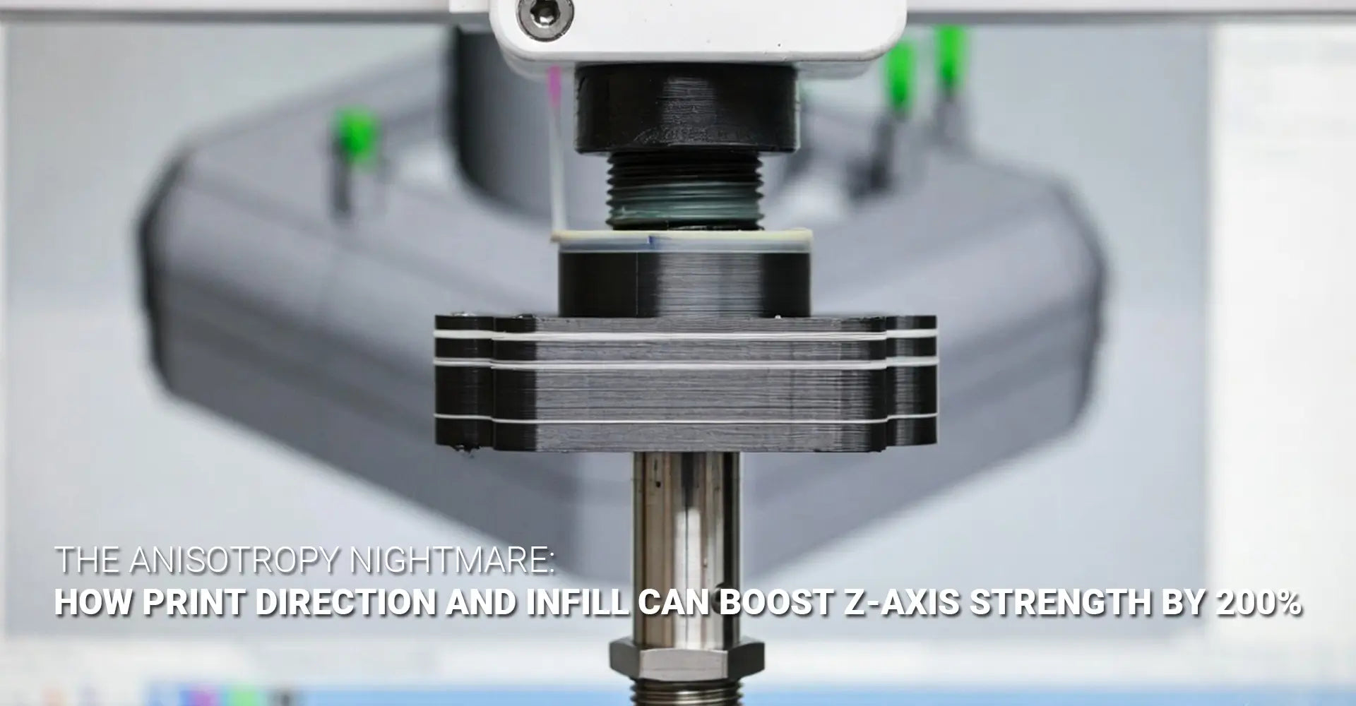
You just spent hours designing the perfect part. You hit print. You wait. And then — snap. It breaks right between the layers, clean as a cracker. Sound familiar? You are not alone. This is one of the most common — and most frustrating — problems in FDM 3D printing. The good news? It is almost always fixable. And the fix starts with understanding why it happens.

⚡ Quick Answer: Why Do 3D Prints Break Between Layers?
3D printed parts break between layers because of a property called anisotropy. FDM builds parts by stacking layers on top of each other. The bonds within each layer are strong — but the bonds between layers are much weaker. This direction-dependent weakness is called Z-axis strength failure. The fastest fix? Reorient your part so the main load runs along the layers, not across them.
Still here? Good — because there is a lot more to it than just flipping your part. In this guide, we will walk through the physics behind layer failure, the four most powerful strategies to fight it, and the cutting-edge 2026 breakthroughs that are changing the game entirely. Whether you are an engineer, a designer, or a procurement manager ordering 3D printed parts at scale — this guide will give you the answers you need.
Table of Contents
- What Is the "Cookie-Cracker" Problem — and Why Does It Keep Happening?
- What Is Actually Happening at the Layer Line When Your Part Fails?
- Does Print Orientation Really Make the Biggest Difference for Z-Axis Strength?
- Which Infill Pattern Actually Gives You the Strongest 3D Printed Parts?
- Conclusion & Action Checklist
What Is the "Cookie-Cracker" Problem in 3D Printing — and Why Does It Keep Happening?
If you have ever posted in a machining or engineering forum about a part that snapped clean between its layers, you are in very good company. Engineers across Reddit, LinkedIn, and manufacturing communities describe the same experience: a part that looks solid, feels solid — and then fails immediately under real-world load. Not because of a bad design. Not because of a bad printer. But because of FDM anisotropy.
🔑 Key Facts at a Glance
| Direction | Strength Level | Notes |
|---|---|---|
| XY Plane (within layer) | 80–100% of nominal material strength | Strong — filament bonds sideways within the layer |
| Z-Axis (between layers) | 60–80% of nominal — sometimes lower | Weak — layers only "weld" partially to each other |
| Worst-case gap | Up to 4–5× difference | A part holding 200 lbs in XY may snap at 50 lbs in Z |
Bottom line: Your 3D print is not the same material in every direction. It is more like wood — and just like wood, it splits along the grain.
So what does "anisotropy" actually mean in plain English? It simply means direction matters. A truly isotropic material — like a block of steel or an injection-molded plastic part — has the same strength no matter which way you pull, push, or twist it. But an anisotropic material like an FDM print is strong in some directions and weak in others.
Think of it like a wooden plank. Pull along the grain — it holds. Pull across the grain — it splits. Your 3D print works the same way. The "grain" is the layer direction. The split happens at the layer line. And that split — that failure between layers — is exactly what turns your part into a cracker.
This is not a quirk of cheap printers or budget filament. It is a fundamental property of how FDM works. Every layer is deposited on top of the previous one. The previous layer has already cooled. The new layer re-melts it slightly — but only slightly. The result is a partial bond, not a full weld. And partial bonds break.
Understanding 3D printing failure modes is the first step. The next step is knowing what is happening at the microscopic level — which brings us to our next section.
What Is Actually Happening at the Layer Line When Your Part Fails?
Most people assume their part broke because of a printer problem. In reality, the failure almost always starts at the layer line — and it starts during the print, not after. To understand why, you need to know what is actually happening inside your part at the molecular level.
⚡ Two Failure Modes — Explained Simply
| Failure Mode | What It Looks Like | What Causes It |
|---|---|---|
| In-Layer Cracking | Part cracks within a single layer, along the filament path | Voids between adjacent filament roads; poor extrusion |
| Interlayer Delamination | Layers separate like pages in a book | Insufficient heat for bonding; too-fast cooling; high Z-load |
Interlayer delamination is the more common and more dangerous of the two — and it is almost always preventable.

Here is what happens step by step. Your nozzle deposits a bead of molten plastic. That bead cools rapidly — especially with the cooling fan running. The next layer arrives and presses down on the cooled surface. The new, hot plastic re-melts the top of the previous layer. But here is the problem: the previous layer has already solidified. The contact zone is thin. The diffusion of polymer chains across the interface is limited. And the result is a bond that is fundamentally weaker than the parent material.
Now add a mechanical load. When you apply force perpendicular to the layers (Z-axis), that load goes directly into the weakest point — the layer interface. Layer bonding techniques like increasing print temperature and slowing down the print speed exist precisely to extend the re-melting window and allow more polymer chain diffusion across the interface.
Those visible layer lines on your print? They are not just cosmetic. They are stress concentrators — geometric features that cause stress to multiply at that point. Every layer line is a tiny notch. Under load, stress concentrates at those notches and propagates into cracks. This is why surface finish matters beyond aesthetics — smoother surfaces mean fewer stress concentrators.
Z-axis strength can be as low as 60–80% of nominal material values under baseline conditions. That gap is not acceptable for structural applications. But the strategies in the next two sections can close it dramatically.
Does Print Orientation Really Make the Biggest Difference for Z-Axis Strength?
Yes. Without question. Print orientation for strength is the single most powerful variable you can control — and it costs you absolutely nothing to change. No new material. No new printer. Just a rotation in your slicer before you hit print.
⚡ The Golden Rule of Orientation
Orient your part so that primary loads run parallel to the layers — not perpendicular to them.
| Scenario | Poor Orientation | Strong Orientation |
|---|---|---|
| Bracket under vertical pull | Printed upright — layers are horizontal, load crosses them | Printed on its side — layers run along the direction of pull |
| Shaft resisting bending | Printed vertically | Printed horizontally — layers run along the shaft axis |
| Hook carrying weight | Hook opening faces up — load crosses layers | Hook opening faces sideways — layers align with the pull |

Load direction alignment is what separates engineers who get strong parts from those who don't. The concept is simple: layers bond well sideways but bond poorly upward. So if your load goes upward through the part (Z-direction), you are relying on the weakest bond. Rotate the part so the load goes sideways through it — and now you are relying on the strong in-layer bond.
A real-world example: a mounting bracket that was printed upright (to minimize supports) kept failing in service. The team rotated it 90° so it printed lying flat. The layers now ran along the length of the bracket, parallel to the pull force. The bracket held 3× more load before failure. Same material. Same printer. Same design. Just a smarter orientation.
For parts with complex, multi-directional loads, the research suggests a 45° orientation often delivers the best balanced result. At 45°, no single layer line is perfectly perpendicular to any one load direction — spreading the stress more evenly across the part. This is especially relevant for automotive components and industrial machinery parts that see vibration, torsion, and impact simultaneously.
Part orientation mechanical properties are also affected by support structures. A part printed in the optimal orientation may need more supports — but that trade-off is almost always worth it for structural applications. Think of the support material cost as cheap insurance against field failures.
Beyond orientation, print parameters make a major difference too:
- Temperature: The +10°C rule — raising nozzle temperature by 5–10°C significantly improves interlayer welding by extending the re-melting window. Test in 5°C increments.
- Print speed: Slower speed gives each layer more time in contact with the hot nozzle zone. Layer adhesion optimization often starts with simply slowing down.
- Layer height: Thinner layers mean more bond interfaces — and more total bond area per unit height. A 0.15 mm layer height typically outperforms 0.3 mm for Z-axis strength.
Which Infill Pattern Actually Gives You the Strongest 3D Printed Parts?
Here is a misconception that costs engineers a lot of failed parts: infill is not just for weight savings. The pattern you choose — and the density you set — has a direct, measurable impact on structural performance in all three directions. Especially the Z-axis.
⚡ Infill Pattern Comparison at a Glance
| Pattern | Strength Direction | Z-Axis Performance | Best For |
|---|---|---|---|
| Gyroid | All directions equally | ✅ Excellent — near-isotropic | Multi-directional loads, cyclic stress |
| Honeycomb | XY-dominant | ✅ Good at 30%+ density — 36.8 MPa recorded | High tensile strength applications |
| Rectilinear / Grid | Two directions only | ❌ Weak — directional bias, stress concentration | Prototypes, non-structural parts |
| Concentric | Along filament path | ✅ Good for load-aligned parts | Torsional and perimeter-dominant loads |
Key data point: Moving from 15% to 30% infill density increases tensile strength by 85–102% — regardless of pattern tested.

Gyroid infill strength stands out for one key reason: its geometry is a 3D wave-like surface with no straight lines and no preferred direction. Unlike rectilinear infill — which is strong in two directions and weak everywhere else — gyroid distributes stress evenly in all directions. This makes it the closest thing FDM has to an anisotropic vs isotropic 3D printing solution: you cannot make FDM perfectly isotropic, but gyroid infill gets you closer than any other standard pattern.
In testing, gyroid achieved 33.1 MPa tensile strength with a 5.50% deformability ratio — the best balance of strength and flexibility of any pattern tested. For cyclic loading (repeated stress, vibration, impact), that combination is ideal. The 3D printing plastics you choose matter here too — different materials respond differently to infill geometry, and the combination of gyroid with a high-performance polymer like PETG or Nylon can be especially effective.
Honeycomb at 30% density recorded the highest tensile strength of any pattern in benchmark testing — 36.8 MPa. If your application requires maximum tensile strength and your loads are somewhat predictable, honeycomb at 30%+ is a strong choice.
Interlayer delamination prevention is also improved by higher infill density, because more infill means more material supporting the top and bottom layers — reducing the chance of void-related delamination.
2026 Breakthroughs: What's Coming Next?
The field is not standing still. Three technologies are pushing beyond what conventional slicer settings can achieve:
- Voxelfill (AIM3D) — Instead of stacking 2D layers, Voxelfill builds components by filling volumetric "voxels" that span across layer boundaries. The voxel fill algorithm effectively eliminates the traditional layer interface by making the build unit 3D rather than 2D. Early results show dramatically more homogeneous strength across all axes.
- Active Z Printing (Non-Planar Layers) — Instead of flat, horizontal layers, Active Z printing deposits material in sinusoidal or curved paths that align with the stress tensors in the part geometry. By keeping the deposition direction aligned with the load direction everywhere in the part — not just on average — stress concentrations at layer lines are dramatically reduced.
- Chemical Interlayer Bonding — New materials incorporating dynamic chemistry at the molecular level can enhance Z-axis strength by up to 150% while leaving XY-plane properties unchanged. These materials are not yet commodity filaments — but they are real, commercially available, and increasingly accessible for demanding applications.
Conclusion & Action Checklist
Anisotropy is not a defect in your printer. It is not a flaw in your design. It is a fundamental property of FDM — and once you understand it, it becomes something you can control rather than something that surprises you.
The difference between a part that snaps like a cracker and one that holds under real load is almost always one of three things: orientation, parameters, or infill. Often all three together.
✅ Your Z-Axis Strength Action Checklist
Step 1 — Orient Smart
- [ ] Identify your primary load direction before you open the slicer
- [ ] Rotate the part so that load runs parallel to layers, not perpendicular
- [ ] For complex loads, try a 45° orientation for balanced performance
- [ ] Accept supports as a trade-off for a stronger orientation
Step 2 — Tune Your Parameters
- [ ] Raise nozzle temperature by 5–10°C and test for better layer adhesion
- [ ] Reduce print speed — especially for the perimeters and top/bottom layers
- [ ] Reduce layer height from 0.3 mm toward 0.15 mm for more bond area
- [ ] Lower or disable cooling fan for materials sensitive to rapid cooling (ABS, ASA, PC)
Step 3 — Choose the Right Infill
- [ ] Use gyroid for multi-directional or unpredictable loads
- [ ] Use honeycomb at 30%+ for maximum tensile strength
- [ ] Stay between 25–40% density for the best strength-to-material ratio
- [ ] Avoid rectilinear and grid for any structural application
Step 4 — Specify Correctly (For Procurement)
- [ ] Require suppliers to document print orientation relative to load direction
- [ ] Specify infill pattern and density — not just material and wall count
- [ ] Request test coupon data in the critical load orientation
- [ ] Ask about layer height and print temperature used
Remember: The goal is not to eliminate anisotropy. The goal is to design with it — so the strong direction is always the one that matters.
📎 Recommended External Resources
[3D printing structural integrity][^1]
[FDM anisotropy][^2]
[anisotropic vs isotropic 3D printing][^3]
[layer adhesion optimization][^4]
[print orientation for strength][^5]
[^1]: This PhD-reviewed design guide covers print orientation strategies, fillet/chamfer implementation, perimeter vs. infill optimization for bending strength, and porosity reduction techniques to maximize printed part strength and isotropy[reference:1].
[^2]: This technical guide explains why FDM prints exhibit anisotropic mechanical properties, comparing them to wood grain, and provides actionable strategies to mitigate Z-axis weakness through optimized print parameters, material selection, and design considerations[reference:2].
[^3]: This data-driven technical article compares isotropic vs anisotropic strength in 3D printing, explaining how layer boundaries create weaker Z-direction interfaces in FDM. It references ASTM D638 and ISO 527 standards for directional tensile testing and provides a detailed comparison of FDM, SLS, and MJF 3D printing against injection molding and CNC machining.
[^4]: Polymaker's official troubleshooting guide covering optimal nozzle temperature, print speed, cooling fan settings, larger nozzle diameters, and filament drying techniques to maximize interlayer adhesion in FDM 3D printing.
[^5]: Shapeways support article explaining how FDM anisotropic behavior affects part strength, with a clear comparison of XY‑plane vs. Z‑axis tensile strength (4–5× difference) and practical recommendations for orienting functional parts to align layer lines with primary loads.
Need help choosing the right process, material, or orientation for your next structural part? Explore Hotean's 3D printing services for engineering-grade production support.


