How Does In-Machine Measurement Stop Tool Wear from Ruining Your CNC Parts?

How Does In-Machine Measurement Stop Tool Wear from Ruining Your CNC Parts?

Every machinist knows the frustration. You set up a job perfectly, the first parts look great, but halfway through the batch, dimensions start drifting. By the time you catch it, you've already made a dozen parts that are barely within tolerance—or worse, scrap. Tool wear sneaks up on you, and before you know it, your profit margin has evaporated along with the accuracy of your cuts.
📊 Quick Answer: What You Need to Know Right Now
| What It Does | How It Helps | Time Saved |
|---|---|---|
| Measures parts automatically inside the machine | Eliminates manual measurement cycles | 5-15 minutes per setup |
| Adjusts tool offsets in real-time | Compensates for tool wear without stopping | Up to 40% less scrap |
| Detects dimensional drift before parts fail | Prevents batch rejection | Enables lights-out operation |
| Validates dimensions post-machining | Confirms quality without CMM checks | 3-8 minutes per part |
Bottom Line: Touch probes act as your digital quality inspector, catching errors before they become expensive scrap. They measure your parts without removing them from the chuck, then tell your CNC turning machine exactly how much to adjust its tool offsets—automatically.
Now that you understand what in-machine measurement does, let's break down exactly how this technology catches errors before they cost you money. This isn't magic; therefore, it's a systematic approach that turns your lathe into a self-correcting production cell.
Table of Contents
- The High Cost of "Good Enough": Why Manual Measurement Is Killing Your Profit?
- How Does the Closed-Loop Workflow Actually Work from Start to Finish?
- What Makes Touch Probes Your Digital Eye Inside the Machine?
- Can Probes Do More Than Just Set Tools at the Beginning?
- How Does the CNC Apply Automatic Compensation Without You Touching Anything?
-
What Real-World Problems Do Machinists Face with Compensation Systems?
The High Cost of "Good Enough": Why Manual Measurement Is Killing Your Profit?
Manual measurement feels safe and familiar. You've been doing it for years, and it works—most of the time. However, the hidden costs add up faster than you might think, especially when you're running CNC machining service operations where every minute counts.
The Real Cost Breakdown
When you stop a machine to measure a part manually, you're paying for more than just the time it takes to grab your calipers. Here's what's actually happening:
- Machine downtime: 3-8 minutes per measurement cycle means lost production capacity
- Operator dependency: Your skilled machinists spend time on repetitive tasks instead of solving complex problems
- Scrap accumulation: Tool wear continues between checks, potentially ruining multiple parts
- Batch delays: Quality holds and rework push delivery dates further out
- Inconsistent results: Human error and measurement technique variations affect reliability

Why "Checking More Often" Doesn't Solve the Problem
Many shops try to avoid scrap by measuring more frequently. Nevertheless, this creates a vicious cycle. The more you stop to measure, the less productive your machine becomes. Meanwhile, you're still only catching problems after they've started affecting parts. Furthermore, each time you remove a part from the chuck for measurement, you risk introducing new errors when you rechuck it.
The math is brutal. If you're running 50 parts per shift and checking every 5 parts, that's 10 measurement cycles at 5 minutes each—nearly an hour of non-productive time. Additionally, you're still vulnerable to the parts made between those checks. This approach doesn't prevent problems; it just helps you discover them slightly faster.
Traditional measurement methods also create a skill bottleneck. Only experienced operators can reliably measure complex features with micrometers and bore gauges. Consequently, your junior staff can't run jobs independently, limiting your shop's flexibility. When your skilled people are tied up with measurement tasks, they're not available for setup, troubleshooting, or training.
How Does the Closed-Loop Workflow Actually Work from Start to Finish?
The term "closed-loop" sounds technical, but the concept is straightforward. Unlike an open-loop system where the machine blindly follows programmed commands, a closed loop turning process continuously checks its own work and corrects errors automatically. Think of it like a thermostat that measures room temperature and adjusts heating accordingly, rather than running the heater for a fixed time and hoping for the best.
The Seven-Step Cycle That Never Stops Working
Here's exactly what happens during each production cycle:
- Rough cut completes: The tool removes material based on the programmed dimensions
- Probe touches part surface: A precision touch probe extends and makes contact with specific measurement points
- Control compares measured vs. programmed dimensions: The CNC calculates the difference between what you wanted and what you got
- System calculates error amount: The control determines exactly how much adjustment is needed
- Tool offset updates automatically: New values write directly to the offset register without operator input
- Finish cut uses corrected offset: The final pass machines the part to the correct dimension
- Final measurement validates result: An optional verification check confirms the part meets specifications
Understanding the Feedback Mechanism
The beauty of this system lies in its continuous feedback. Each measurement informs the next cut, creating a self-regulating process. Moreover, the system learns from every part it makes. If tool wear is gradually increasing diameter readings, the compensation adjusts incrementally to maintain consistency across the entire production run.
This on-machine probing compensation happens faster than you can manually measure a single dimension. While a machinist might take 3-5 minutes to check a part with hand tools, the probe completes its measurement cycle in 5-15 seconds. Therefore, you get more frequent checks without sacrificing productivity—in fact, you gain productivity because the machine never stops for manual inspection.
The control stores measurement data in memory variables that persist throughout the program. These variables feed into conditional logic statements that determine when compensation is necessary. For instance, you can program the system to only adjust offsets when the measured error exceeds 0.0005", preventing unnecessary micro-adjustments that might introduce instability. Similarly, you can set maximum limits that trigger an alarm if something goes seriously wrong, like a tool breaking or a workpiece coming loose.
The coordinate system makes all of this possible. When the probe touches the part, it records the exact machine coordinates at the moment of contact. By comparing these coordinates to the programmed target position, the control calculates the error vector—both magnitude and direction. This information flows directly into offset calculations, ensuring corrections happen in the right direction and by the right amount.
What Makes Touch Probes Your Digital Eye Inside the Machine?
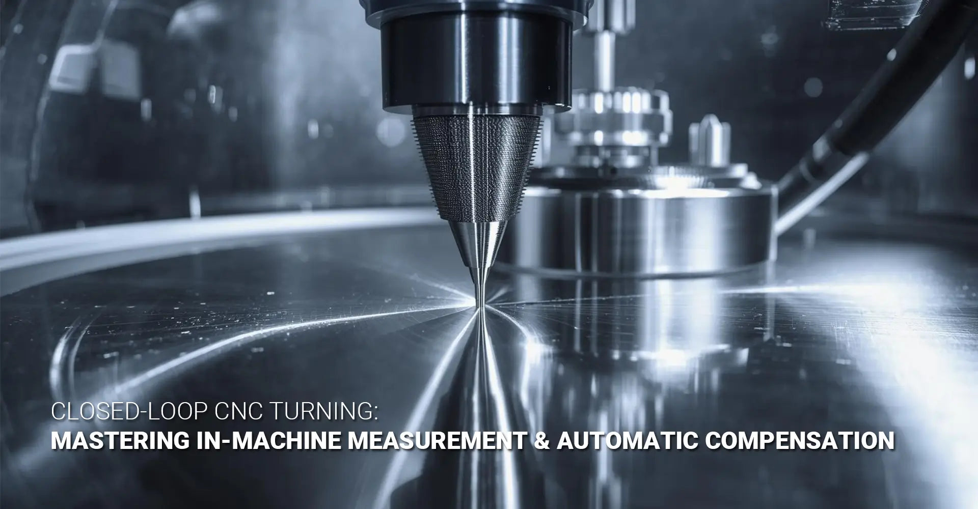
A touch probe isn't just a fancy measurement tool; instead, it's a precision sensor that transforms your lathe into a coordinate measuring machine. While traditional industrial machinery requires external quality checks, probing brings measurement directly to the point of production.
Performance Comparison: Probe vs. Manual Tools
| Measurement Method | Repeatability | Speed | Operator Skill Required | Works with Coolant |
|---|---|---|---|---|
| Touch Probe | ±0.001" | 2-5 seconds | Minimal | Yes |
| Micrometer | ±0.003" | 2-5 minutes | High | No |
| Caliper | ±0.005" | 1-3 minutes | Medium | No |
| Bore Gauge | ±0.0005" | 3-8 minutes | Very High | No |

How the Technology Actually Works
The probe stylus consists of a precision ball mounted on a spring-loaded or strain gauge mechanism. When the ball contacts the workpiece, it deflects slightly—typically just a few thousandths of an inch. This deflection triggers an electronic signal that the CNC control receives almost instantaneously. The control then captures the exact machine coordinates at that trigger moment.
This mechanism provides incredible repeatability because it eliminates human variables. Your hand pressure on a micrometer, your viewing angle on a dial indicator, your technique with inside calipers—none of these factors affect probe measurements. Additionally, the probe doesn't care about temperature variations in the shop, lighting conditions, or operator fatigue. It delivers the same accuracy on the first part of the shift and the last.
Calibration is critical for maintaining this accuracy. Before using the probe, you must calibrate it against a reference sphere of known diameter. The control uses this calibration to account for the probe ball radius and any geometric offsets. Furthermore, you should recalibrate periodically—many shops do this at the start of each shift or whenever they change probe tips.
The touch probe cycle turning programming typically includes approach vectors, clearance distances, and feed rates. The probe must approach the part surface at a controlled speed to avoid bouncing or damaging the delicate stylus. Most controls offer built-in probe cycles that handle these details automatically, but understanding the underlying logic helps you troubleshoot problems and customize cycles for unusual geometries.
Can Probes Do More Than Just Set Tools at the Beginning?
Many machinists think probes are only useful for initial tool setting, but that's selling the technology short. In reality, probing systems handle multiple critical tasks throughout the production process, making your CNC metals plastics machining operations more reliable and autonomous.
Three Game-Changing Applications
Mid-Process Checks: This is where in-process measurement turning truly shines. Instead of waiting until a part is finished to discover a problem, you can program measurement cycles between roughing and finishing operations. For example, after rough turning an outer diameter, the probe checks the dimension before the finish cut. If the rough cut left too much or too little material, the system adjusts the finish tool offset accordingly. This prevents scenarios where a rough tool crashes into the work because it's wearing faster than expected.
Post-Process Validation: Once the part is complete but still in the chuck, the probe can verify critical dimensions automatically. This creates a documented quality record without requiring a trip to the CMM. Moreover, you can program decision logic: if the part passes, eject it to the finished parts bin; if it fails but is within rework tolerance, eject it to a rework bin; if it's hopelessly out of spec, halt the machine and alert the operator. This automated sorting saves hours of manual inspection time.
Wear Trending: The most sophisticated application involves tracking tool wear patterns across multiple parts. By measuring the same feature on every part (or every tenth part), you can plot how the tool is degrading over time. Therefore, you can predict when a tool change will be necessary rather than waiting for a part to go out of tolerance. This predictive approach minimizes scrap and maximizes tool life because you replace inserts at the optimal moment.
Programming Strategies for Advanced Applications
Mid-process checks require careful timing. You need to program the measurement cycle after the tool has cleared the part but before the next operation begins. Additionally, you must account for thermal effects—a part measured immediately after a heavy roughing pass might give different readings than one that's had time to cool. Some machinists program a brief dwell or run coolant for a few seconds before probing to stabilize temperatures.
Post-process validation becomes powerful when combined with statistical process control. You can program the control to calculate running averages, detect trends, and identify when a process is drifting toward a tolerance limit before any parts actually fail. This forward-looking approach catches problems early, when corrective action is still simple.
Wear trending works best with consistent measurement locations. Pick a dimension that's easy to measure reliably—a simple diameter or face is better than a complex profile. Then measure it on every part or at regular intervals. Store the data in memory variables or export it to a network location where you can analyze it with spreadsheet software or dedicated SPC programs.
How Does the CNC Apply Automatic Compensation Without You Touching Anything?
The term "automatic" seems like magic until you understand what's happening behind the scenes. Your CNC control is constantly reading, calculating, and writing values to specific memory locations called tool offset registers. This is where automatic tool offset CNC functionality lives—in the systematic manipulation of these registers based on measurement data.
Understanding Offset Registers
Every CNC control maintains a table of tool offsets. Each tool in your turret has at least two offset values: a geometry offset (the physical location of the tool tip) and a wear offset (adjustments for gradual tool degradation). When your program calls for a tool, the control adds these offset values to the programmed coordinates to determine where the tool actually moves.
Here's the critical concept: tool wear compensation CNC systems work by automatically updating the wear offset register after each measurement cycle. The geometry offset remains constant because the tool's physical mounting position doesn't change. However, the wear offset increases gradually as the cutting edge dulls and the tool "grows" effectively shorter or larger depending on whether you're turning an ID or OD.
The math is straightforward. If you program a 2.000" diameter but the probe measures 2.003", you have a +0.003" error. For an OD turning operation, the control subtracts 0.0015" from the tool's wear offset (half the diameter error equals the radius adjustment). On the next pass, the tool will cut deeper, bringing the part diameter down to the target dimension.
Safety Limits and Logic Controls
Automatic compensation isn't completely autonomous—you program safety boundaries to prevent disasters. Most shops set maximum adjustment limits. For example, you might allow the system to compensate up to 0.010" automatically, but if the measured error exceeds that value, the machine halts and alerts the operator. This prevents the system from trying to "fix" a catastrophic problem like a broken tool or incorrect raw material by making enormous offset adjustments that could crash the tool or ruin the part.
Conditional programming enhances this safety. You can write logic that says: "If measured error is between 0.0002" and 0.005", apply compensation. If error is less than 0.0002", do nothing (already within tolerance). If error exceeds 0.005", stop and alarm." This creates intelligent decision-making rather than blind automatic adjustment.
Macro Programming Examples
Most modern controls support macro programming languages (like Fanuc's Custom Macro B or Siemens' CYCLE programming) that enable sophisticated compensation logic. Here's a simplified example of what the code might look like:
#100 = 2.000 (Target diameter)
G31 X2.1 F10 (Probe move until contact)
#101 = #5061 (Store measured X position)
#102 = #100 - #101 (Calculate error)

IF [#102 GT 0.010] GOTO 9000 (Error too large, alarm)
IF [#102 LT 0.0002] GOTO 100 (Within tolerance, skip compensation)

#110 = #102 / 2 (Convert diameter error to radius)
#43 = #43 - #110 (Adjust tool wear offset)

N100 (Continue program)
N9000 M0 (Stop for operator intervention)
This logic measures a diameter, compares it to the target, checks if the error is reasonable, and applies the appropriate compensation. Furthermore, it documents decision points clearly, making troubleshooting easier when something goes wrong.
What Real-World Problems Do Machinists Face with Compensation Systems?
Implementation isn't always smooth, and pretending otherwise doesn't help anyone. The machining communities, particularly discussions on platforms like r/Machinists, reveal common pitfalls that trip up even experienced shops when they first adopt CNC turning in-machine measurement compensation technology.
The Four Most Common Failure Modes
1. Probe Calibration Errors
A mis-calibrated probe is worse than no probe at all because it generates confidently wrong measurements. The most common mistake is calibrating with a dirty or damaged calibration sphere. If there's a chip stuck to the sphere, your calibration will be off by however tall that chip is—and every subsequent measurement will inherit that error.
Another frequent problem involves incorrectly entering the sphere diameter. If you calibrate with a 10mm sphere but tell the control it's 10.5mm, all your radius calculations will be wrong. Additionally, calibration degrades over time as the probe stylus wears or gets slightly bent. Therefore, regular recalibration isn't optional; it's essential for maintaining accuracy.
2. Chip Interference
Metal chips are the nemesis of probing systems. A single chip on the part surface or stuck to the probe ball will cause a false trigger, making the control think it's touched the part when it's actually touching a chunk of swarf. The resulting measurement will be wildly inaccurate, potentially leading the system to make catastrophic compensation adjustments.
The solution involves high-pressure coolant and air blast. Before any measurement cycle, flood the area with coolant to wash away chips, then blast it with high-pressure air to clear any remaining debris. Some shops program automatic air blast cycles that pulse air across the measurement area for 2-3 seconds before the probe moves in. This simple step prevents most chip interference problems.
3. Unstable Workholding
If the part moves during probing, your measurement becomes meaningless. This seems obvious, but subtle workholding issues often go unnoticed. A weakening jaw spring, worn chuck jaws, insufficient clamping force—any of these can allow the part to shift slightly when the probe touches it. Moreover, long, slender parts may deflect under probe pressure if they're not adequately supported.
The test is simple: Set up the probe to measure the same feature repeatedly (ten times in a row) without cutting anything. If you get identical readings within 0.0002", your workholding is solid. If readings vary by 0.001" or more, you have a stability problem that must be fixed before compensation can work reliably.
4. Poor Programming Logic
Probe approach angles matter tremendously. If you approach perpendicular to a surface, you get accurate measurements. However, if you approach at an angle, the stylus might slide along the surface before triggering, giving you a reading that's off by the distance it slid. Similarly, approaching too fast can cause the stylus to bounce off the surface, creating false triggers.
Clearance distances also create problems. If your probe doesn't retract far enough between measurement points, it might drag across the part surface, bending the stylus or triggering accidentally. Conversely, excessive clearances waste cycle time. Finding the optimal balance requires testing and refinement.
Learning from Failure: Troubleshooting Strategies
When compensation results are inconsistent, work through a systematic diagnosis. First, verify calibration with a known artifact—a gage block or ring gage. Second, watch the probe during measurement cycles to spot chip interference or unusual approach behavior. Third, check your offset table to confirm compensation is actually updating the values you think it's updating. Finally, review your program logic line by line to catch mathematical errors or conditional statements that don't trigger properly.
Experienced machinists recommend starting simple. Get single-point measurement and compensation working reliably before attempting complex multi-point measurement cycles. Master compensation on simple diameters and faces before tackling profiles, tapers, or radii. Build your confidence and your understanding incrementally rather than trying to implement everything at once.
Documentation is your friend. Keep a log of what compensation values the system is applying and how parts are measuring as a result. This creates a data trail you can analyze to identify patterns. If every tenth part suddenly requires a large compensation, you likely have an intermittent problem like chip interference. If compensation gradually increases over time, that's normal tool wear. The data tells the story if you're collecting and reviewing it regularly.
Conclusion
In-machine measurement compensation transforms CNC lathes from simple cutting tools into intelligent, self-correcting production systems. By automatically measuring parts and adjusting tool offsets in real time, this technology eliminates the manual measurement bottleneck that has plagued machine shops for decades. Moreover, it compensates for the inevitable realities of tool wear, thermal drift, and material variation—factors that no amount of careful setup can completely prevent.
The financial benefits are clear and measurable. Reduced scrap rates, elimination of measurement-related downtime, and the ability to run unattended for extended periods all contribute to rapid return on investment. For many shops, the system pays for itself within a few months through improved overall equipment effectiveness alone. Furthermore, the technology levels the playing field between experienced operators and newer staff, reducing the skill bottleneck that limits production flexibility.
However, success requires more than just buying a probe and installing it. As we've seen from real-world implementations, proper calibration, clean measurement conditions, stable workholding, and intelligent programming logic are all essential. The system is precise and reliable, but only when you treat it as the precision instrument it is rather than as a brute-force solution.
This technology isn't about replacing skilled machinists. Instead, it frees them from repetitive measurement tasks so they can focus on what humans do best: programming, troubleshooting, process improvement, and solving the complex problems that machines can't handle alone. The probe handles the tedious, repetitive validation work, while your skilled people drive innovation and efficiency gains.
If you're still relying on manual measurement between every few parts, you're competing with one hand tied behind your back. The shops that have adopted in-machine measurement are already running longer, faster, and more accurately. The question isn't whether this technology works—thousands of installations prove it does. The question is how much longer you can afford to wait before joining them.
External Links & Resources
[CNC turning in-machine measurement compensation][^1]
[Closed loop turning process][^2]
[In-process measurement turning][^3]
[Automatic tool offset CNC][^4]
---
[^1]: Understanding this concept is crucial for improving precision in CNC machining, ensuring better product quality.
[^2]: Exploring this topic can enhance your knowledge of automated machining systems, leading to increased efficiency and accuracy.
[^3]: Understanding in-process measurement turning can enhance your CNC machining efficiency and accuracy.
[^4]: Exploring automatic tool offset can help you optimize your CNC operations and reduce setup time.


