How Chipbreaker Design Solves The Chip Tangle of CNC Turning Stainless Steel 316?

How Chipbreaker Design Solves The Chip Tangle of CNC Turning Stainless Steel 316?

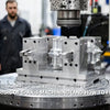
You start a new batch of 316 stainless parts. Within minutes, a long ribbon of swarf wraps tightly around your turret. The machine alarms. You stop. You clear it by hand. Then it happens again. If you run CNC turning stainless steel on a regular basis, you already know this frustration. The 'bird's nest' problem is one of the most-reported issues on machinist forums worldwide. And it is not just annoying — it costs you time, tooling, and money.
The short answer:
316 stainless steel creates long, stringy chips because of its high ductility and work-hardening nature. To fix this, you need three things working together:
- Chipbreaker insert geometry — physically curls and fractures chips at the source
- High-pressure coolant — hydraulically breaks chips and controls heat
- Smart coatings and programming — reduce friction and force fracture when all else fails
Keep reading. By the end of this article, you will have a clear, step-by-step plan to eliminate chip tangles for good.
But before we jump into solutions, it helps to understand why 316 behaves so differently from other stainless grades like 303 or 304. Once you understand the root cause, every solution we cover will make perfect sense.
Table of Contents
- Why Does CNC Turning Stainless Steel 316 Create Such a Tangled Mess?
- What Chipbreaker Insert Geometry Actually Does for Stainless Steel Chip Control?
- Does High Pressure Coolant Really Solve the Stringy Chips Stainless Steel Problem?
- When Standard Methods Fail — What Are the Advanced Chip Breaking Techniques?
- Conclusion
- FAQ
Why Does CNC Turning Stainless Steel 316 Create Such a Tangled Mess?
Every machinist who has run 316 stainless machining jobs knows the scene. You walk up to the machine and see a shiny, tangled pile of swarf wrapped around everything. It looks like a bird built a nest inside your lathe. This is not bad luck. It is physics.
Here is the key point:
316 stainless steel is an austenitic alloy. It has very high elongation and toughness. That means chips stretch instead of snap. They form long, continuous ribbons — sometimes several feet long — before detaching. Proper swarf management starts with understanding this material behaviour.

The Metallurgy Behind the Mayhem
So why exactly does 316 act this way? Let's break it down simply.
First: High ductility. 316 has a face-centred cubic (FCC) crystal structure. This structure allows metal atoms to slide past each other without breaking. Result? Long, stretchy chips that don't fracture.
Second: Work hardening. As the cutting tool moves through 316, the material in front of the tool gets harder. This is called work hardening. The chip itself becomes harder and tougher as it forms — making it even less likely to break.
Third: Low thermal conductivity. 316 does not conduct heat well. Heat builds up at the cutting edge instead of dissipating. This worsens chip ductility and accelerates tool wear.
Fourth: Molybdenum content. Unlike 304, 316 contains molybdenum (Mo). This improves corrosion resistance — but it also adds toughness, compounding the chip problem.
Together, these four factors create stringy chips stainless steel machinists dread. Standard insert grades and conventional flood coolant simply cannot overcome this combination. You need a targeted approach — which we cover in the next sections.
What Chipbreaker Insert Geometry Actually Does for Stainless Steel Chip Control?
The first — and most important — line of defence against tangled chips is your insert. Specifically, the chipbreaker geometry on your cutting insert. Most machinists use general-purpose inserts for 316 and wonder why they keep getting bird's nests. The answer is almost always the wrong chipbreaker.
Quick answer:
Chip breaking inserts for stainless steel use a specifically shaped land — a small step or groove behind the cutting edge — to redirect chip flow. As the chip curls over this land, it bends tightly until it snaps. The chip breaks into short segments before it can wrap around anything.
Key chipbreaker types for 316 stainless:
- TH geometry: Designed specifically for austenitic stainless. Sharp cutting edge with optimised land angle. Produces tight chip curl at low-to-medium feeds.
- MM geometry: Balanced between chip control and edge strength. Good for medium roughing passes in 316.
- Finishing geometries: Very sharp edge, minimal land. Ideal for tight tolerances but need higher precision in parameter selection.
Selecting the Right Chipbreaker for Roughing vs. Finishing in 316
Choosing the wrong chipbreaker for your cut type is one of the most common mistakes in CNC machining service operations involving 316. Here is how to match your chipbreaker to the task:
For roughing (high depth of cut, high feed rate):
- Use a stronger geometry with a wider land width — this prevents edge chipping during heavy cuts.
- Prioritise chip control over surface finish at this stage.
- A grade like NTK's ST4 with MM or TH chipbreaker performs well in roughing 316.
For finishing (light cuts, tight tolerances):
- Use a sharper, more aggressive chip-curl geometry.
- Focus on surface finish. A positive rake angle keeps cutting forces low and reduces work hardening.
- Be aware: what works in roughing often fails in finishing — and vice versa.
Additionally, consider CBN/PVD coated inserts for 316. PVD (Physical Vapour Deposition) coatings maintain a sharper cutting edge than CVD coatings. This is critical for stainless — a sharp edge reduces cutting forces and limits work hardening. CVD coatings are thicker and better for heat resistance, but they dull the edge slightly. For 316, PVD is usually the better choice for both roughing and finishing.
Real-world result: ST4 grade with TH chipbreaker achieved 30,000 parts per corner in stainless turning applications — approximately 50% longer tool life compared to competing grades. This kind of performance has a direct impact on cost-per-part.
Does High Pressure Coolant Really Solve the Stringy Chips Stainless Steel Problem?
Many machinists assume their flood coolant is doing the job. They see coolant flowing over the workpiece and think it is reaching the cutting zone. In 316 stainless turning, this assumption is wrong — and it is costing you chips, tool life, and downtime.
The direct answer:
High pressure coolant turning (700–1,015 PSI) delivers coolant directly to the insert-chip interface. Standard flood coolant operates at 30–100 PSI. At that pressure, it simply cannot penetrate the cutting zone in 316. High cutting pressures create a steam barrier that blocks conventional coolant entirely. High-pressure systems punch through that barrier. The result: hydraulic chip breaking, lower temperatures, and dramatically longer tool life.
How Through-Tool Coolant Hydraulically Breaks Chips
Systems like Tungaloy's TungTurn-Jet are designed specifically for stainless and exotic alloys. They deliver a high-velocity coolant jet directly at the insert tip through a channel in the toolholder. This jet does three things at once:
- Hydraulic chip breaking: The coolant jet physically lifts the chip away from the rake face, thinning it and helping it fracture into short segments.
- Thermal control: The coolant reaches temperatures close to 1,000°C at the cutting zone. High-pressure delivery removes this heat before it can soften the tool or work-harden the workpiece surface.
- Lubrication at the source: Standard coolant lubricates the top of the chip, not the cutting interface. Through-tool coolant lubricates exactly where it matters most.
Can you retrofit high-pressure coolant to an existing lathe?
Yes — but it requires planning. You will need:
- Through-tool coolant toolholders (such as Tungaloy's TungTurn-Jet series)
- A high-pressure pump unit — typically $10,000 to $25,000
- Proper filtration to handle higher flow rates without blocking the coolant channels
For Swiss-type lathes used in industrial machinery applications, many manufacturers offer integrated high-pressure systems as factory-fitted options. If you are purchasing a new machine, always ask about high-pressure coolant capability upfront.
When Standard Methods Fail — What Are the Advanced Chip Breaking Techniques?
Sometimes you have the right chipbreaker. You have high-pressure coolant. And chips are still giving you trouble. This happens in interrupted cut stainless applications, parts with variable diameters, or thin-wall components where chip control is especially unpredictable. In these cases, it is time to go further.
The quick summary:
Advanced chip breaking uses the machine itself to force chip fracture. Two main technologies do this: Low Frequency Vibration (LFV) cutting and Step-Cycle programming. Both introduce controlled oscillations into the cutting axis. This creates a brief 'air cut' moment — the chip thins and fractures into short, safe pieces.
LFV Cutting and Step-Cycle Programming Explained
Low Frequency Vibration (LFV) — Citizen Machinery
LFV is a built-in machine function available on select Citizen CNC lathes. It overlays a controlled sinusoidal oscillation onto the Z-axis movement. Here is what happens step by step:
- The tool advances, then briefly retreats by a tiny amount (a fraction of a millimetre).
- On the retreat phase, the chip loses contact with the cutting edge for a fraction of a second.
- This creates a stress point in the chip — it fractures into short segments automatically.
- Cycle time increases slightly, but machine stops for chip clearing are eliminated.
Step-Cycle Programming (SCP) — STAR Micronics
STAR's Step-Cycle-Pro achieves a similar result through G-code oscillation commands. It is more flexible than LFV because it can be applied selectively to specific operations within a program.
Material matters too: Ca-Treated 316L Stainless
Research shows that calcium (Ca) treatment of 316L can improve chip breakability in 80% of cutting trials. Ca modification affects non-metallic inclusions in the steel, making chips more likely to fracture on their own. If you have control over material sourcing — for example, in automotive or precision components — specifying Ca-treated 316L can significantly improve chip control without changing any machining parameters.
The Valve Stem Case Study
Valve stem machining is a perfect example of where all these techniques converge. 316 valve stems are long, thin, and require consistent surface finish over many thousands of parts. A shop producing 316 valve stems faces: high L/D ratio (vibration risk), continuous chip formation, and strict dimensional tolerances. The winning approach for this application combines: a PVD-coated insert (e.g., ST4 grade) with TH chipbreaker, through-tool high-pressure coolant, and LFV or SCP for the finishing pass on the stem OD. This stack has demonstrated 30,000+ parts per corner with no manual chip clearing between cycles.
Your 'No-Tangle' Checklist for 316 Stainless Turning:
- Insert: PVD-coated grade with TH or MM chipbreaker geometry
- Coolant: High-pressure through-tool system (700–1,015 PSI minimum)
- Parameters: Use manufacturer recommendations specific to 316 — not 304 or 303
- Programming: Enable LFV or SCP for finishing passes on difficult features
- Material: Specify Ca-treated 316L where possible
- Monitoring: Run the first 50 parts attended — then optimise for lights-out operation
Conclusion
Tangled chips in 316 stainless turning are not inevitable. They are a solvable engineering problem — one that becomes straightforward once you understand the material and apply the right tools.
Here is what we covered in this article:
- 316's metallurgy explains the long, stringy chips. High ductility + work hardening = ribbons, not segments.
- Chipbreaker geometry is your first line of defence. TH and MM chipbreakers are engineered for exactly this material.
- High-pressure coolant (700–1,015 PSI) breaks chips hydraulically and controls heat where it matters most.
- PVD coatings keep your edge sharp and reduce friction — directly improving chip separation.
- LFV / Step-Cycle programming solves the edge cases — interrupted cuts, thin walls, and high-volume runs that need lights-out capability.
- Ca-treated 316L is a materials-level solution that improves breakability in 80% of trials.
When these layers work together, machines run unattended, tool life improves, and part quality becomes consistent. For high-volume 316 production, the payback is often measured in months — not years.
The key takeaway is simple: stop treating 316 like 304. It needs its own insert grade, its own chipbreaker, and its own coolant strategy. Once you make that shift, the bird's nest problem disappears.
Ready to Solve Your 316 Chip Control Problems?
Our team at Hotean specialises in precision CNC turning stainless steel for demanding applications across industrial machinery, automotive, and high-precision sectors. Whether you need a quick consultation on tooling selection or a full production solution for 316 stainless parts, we are here to help.
Contact us today to discuss your project. Tell us your part, your current chip problem, and your target volume — and we will come back with a concrete recommendation.
Frequently Asked Questions (FAQ)
Q: Why does 316 stainless steel create such long, stringy chips?
A: It comes down to material science. 316 is an austenitic stainless steel with high elongation and toughness. Chips don't fracture naturally — they form long ribbons. Additionally, 316 work-hardens during cutting, making those chips even harder and tougher to break.
Q: What is the single most effective way to break chips in 316 turning?
A: A combination of specialized chipbreaker geometry and high-pressure coolant delivers the best results. Chipbreakers like the 'TH' series curl chips tightly until they snap. Paired with through-tool coolant at up to 1,015 PSI, the hydraulic force lifts and breaks chips while reducing heat.
Q: What are 'violent' or mechanical chip breaking methods?
A: These include Low Frequency Vibration (LFV) cutting and Step-Cycle programming. Both introduce controlled axis oscillations during turning. Each oscillation creates a brief 'air cut' — the chip thins and fractures into short, safe segments. No operator intervention needed.
Q: Does coolant pressure really matter if I already have flood coolant?
A: Absolutely. Standard flood coolant (30–100 PSI) cannot penetrate the cutting zone in 316. High-pressure systems (700–1,500 PSI) deliver coolant directly to the insert-chip interface. This provides three benefits: hydraulic chip breaking, reduced friction heat, and improved tool life.
Q: What insert grade and chipbreaker should I start with for 316 valve stems?
A: Look for a PVD-coated grade optimized for stainless with a positive chipbreaker geometry. For roughing, use a stronger edge with more land; for finishing, use a sharper geometry with aggressive chip curl. Verified grades like ST4 with TH chipbreaker have shown up to 30,000 parts per corner in stainless applications.
Q: Does the specific 316 alloy variant affect chip breakability?
A: Yes, significantly. Calcium (Ca)-treated 316L improved chip breakability in 80% of cutting trials. Ca modification alters non-metallic inclusions in the steel, making chips more likely to fracture — without changing any machining parameters.
Q: Can I retrofit high-pressure coolant to my existing CNC lathe?
A: Yes, but with planning. You will need through-tool coolant toolholders, a high-pressure pump unit (typically $10,000–$25,000), and proper filtration. Many Swiss-type lathe manufacturers offer integrated high-pressure systems as factory options.
Q: What is the most common mistake machinists make with 316?
A: Running the same parameters as 304 or 303 stainless. 316 requires different speeds, feeds, and chipbreaker selection. Running too slow causes work hardening; too fast with the wrong chipbreaker produces endless strings. Always use insert manufacturer recommendations specifically for 316.
Q: Does pecking or dwell help with chip breaking in turning?
A: No — and it can damage the insert. Unlike drilling, turning requires continuous optimized chip formation. Dwell or rapid feed changes cause work hardening on the cut surface and can lead to insert chipping on re-entry. Use constant feed with optimized chipbreaker geometry instead.
Q: What is the ROI for investing in better chip control for 316 stainless?
A: The savings come from unattended operation and reduced downtime. Shops without proper chip control typically need an operator watching for tangles. With chipbreakers, high-pressure coolant, or LFV technology, machines can run lights-out. For high-volume 316 production, payback is often measured in months.
Recommended External Resources
[CNC turning stainless steel][^1]
[stainless steel chip control][^2]
[316 stainless machining][^3]
[high pressure coolant turning][^4]
[stringy chips stainless steel][^5]
[^1]. A comprehensive technical guide from Seco Tools that explores advanced strategies for machining various stainless steel alloys, focusing on tool wear monitoring and optimal cutting parameters to enhance productivity in CNC turning operations.
[^2]. An expert article published by Fastenal in collaboration with Sandvik Coromant, detailing cutting-edge techniques for managing stringy chips and heat generation through high-pressure coolant and specialized tool geometries during stainless steel machining.
[^3]. A detailed technical resource provides a comprehensive overview of 316 stainless steel properties and specific machining intricacies, offering practical guidelines on maintaining edge sharpness and managing work hardening during fabrication.
[^4]. An authoritative knowledge base article explains the strategic implementation of high-pressure coolant systems in turning operations to achieve superior chip control, reduced cutting temperatures, and increased metal removal rates.
[^5]. An insightful technical blog addresses the challenges of machining gummy materials like stainless steel, offering practical solutions for managing long, stringy chips through optimized coolant application, running parameters, and climb milling strategies.


