Why Your 3D Printed Hook Snaps Like a Wafer Biscuit: A Print Orientation Guide for Stronger Parts?
Why Your 3D Printed Hook Snaps Like a Wafer Biscuit: A Print Orientation Guide for Stronger Parts?
You printed a hook. It looked perfect. Then you hung something on it, and it snapped clean apart, layer by layer, just like a wafer biscuit breaking in half. If this sounds familiar, you are not alone. This is one of the most common failures in 3D printing manufacturing, and it happens for one simple reason: the part was printed in the wrong direction for the load it needed to carry.
The good news is that this problem has a clear fix. Once you understand how layers bond together, you can stop guessing and start printing parts that actually hold up under real-world stress.

Quick Answer: Most 3D printed parts break because their layers are weaker in one direction than another. This is called anisotropy. The fix is simple: orient your part so the layers run with the load, not against it. Studies show the Z-axis, the direction between stacked layers, can be up to 4 to 5 times weaker than the XY plane. Align your print so the force travels along the strong direction, and the part becomes far more reliable.
So why does this happen in the first place, and how do you apply this rule to your own parts? Let's break down the science behind layer strength, then walk through exactly how to orient, design, and source parts that will not fail on you. Whether you are printing a small hook or sourcing load-bearing components through rapid prototyping, the same rule applies every time.
Table of Contents
- The Wafer Biscuit Problem: Why Your Hook Snaps Along the Layers
- Understanding Anisotropy: Why XY Strength and Z-Strength Are Not the Same
- The Golden Rule: How to Orient Parts So Layers Align with the Load
- Materials, Design, and Procurement: Supporting Strategies for Stronger Prints
- Conclusion
The Wafer Biscuit Problem: Why Your Hook Snaps Along the Layers?
Picture a stack of pancakes. Each pancake sticks to the one below it, but that bond is never as strong as the pancake itself. Now imagine pulling that stack apart from the top and bottom. It splits at the seams first, not through the middle of any single pancake. That is exactly what happens inside a 3D printed part.
Quick Answer: This failure is called delamination. It happens when the layers of a print separate along the Z-axis, which is the vertical build direction, instead of holding together under stress.

Here is what happens on a deeper level. A 3D printer builds a part one thin layer at a time. Each new layer is deposited on top of the last one, and heat causes them to fuse together. However, this fusion is never as strong as the plastic within a single layer. As a result, layer-by-layer failure becomes the most common breaking point for parts that are not designed with orientation in mind.
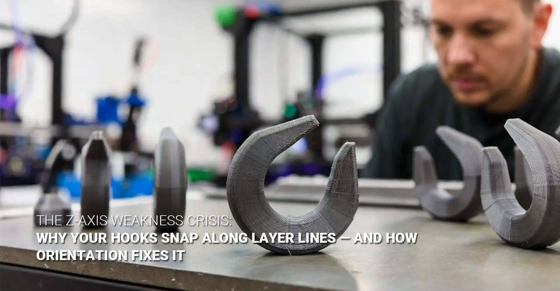
Think about that hook again. If it was printed standing straight up, with layers stacked like a tower, then a hanging weight pulls directly across those weak layer seams. The part is essentially designed to fail. Reddit's maker community has documented this exact scenario countless times, and it remains one of the top complaints from anyone new to functional 3D printing.
Understanding this failure mode is the first step. Next, let's look at the actual numbers behind why this weakness exists, and just how big the gap really is.
Understanding Anisotropy: Why XY Strength and Z-Strength Are Not the Same?
Not all directions inside a 3D printed part are created equal. This property is called anisotropy, and it is the single most important idea to understand before you design or order any load-bearing part.
Quick Answer: The XY plane, which runs along a single printed layer, is strong because the plastic filament stays continuous. The Z-axis, which runs between stacked layers, depends on heat bonding alone, and that bond is significantly weaker.
Research backs this up clearly. Across multiple mechanical tests, parts printed with their layers running perpendicular to the load consistently showed the lowest strength results. In several studies, the gap between XY and Z strength reached 4 to 5 times. That means a part strong enough to hold ten pounds in one direction might snap under just two pounds if the load hits it from the wrong angle.
This happens because of Z-axis layer adhesion. When plastic is extruded, the surface of each new layer must partially melt into the layer below it. If that bond does not form completely, tiny gaps remain between layers. Under stress, those gaps become cracks, and cracks lead to complete separation.
This is also why FDM layer bonding quality varies so much between printers, materials, and even print speed settings. A slower print with more heat often bonds layers better than a rushed one. But even with perfect settings, the Z-axis will still be the weaker direction. That is simply the nature of building something layer by layer.
There is also a well-documented difference between how parts are oriented flat versus on their edge. Testing has shown that specimens printed on-edge can show up to a 389 percent increase in interfacial toughness compared to the same part printed flat. This single design choice can be the difference between a part that holds and one that shatters.
Understanding this weakness is only half the battle. The real value comes from knowing how to use it to your advantage, which brings us to the golden rule of print orientation.
The Golden Rule: How to Orient Parts So Layers Align with the Load?
Once you understand that one direction is weak and one is strong, the fix becomes almost simple. You just need to make sure the weak direction never faces the force.
Quick Answer: Always orient your print so the layers run parallel to the load, not across it. This is the golden rule behind print orientation for strength, and it applies to nearly every functional 3D printed part.
Let's go back to our hook example. If you print it standing upright, the layers stack horizontally, and any hanging weight pulls straight across those weak seams. But if you print the same hook lying on its side, often called the "on-edge" orientation, the layers now run along the length of the hook. The pulling force travels within the layers instead of between them.
This single change is often called load direction alignment, and it is the most reliable form of interlayer delamination prevention available to any maker or manufacturer. You are not changing the material. You are not changing the design. You are simply rotating the part before it prints, and that alone can make the difference between a part that holds for years and one that fails on day one.
This rule does not only apply to hooks. Brackets, clips, load-bearing brackets, and structural mounts all benefit from the same logic. Before you print or order any part, ask a simple question: where is the force coming from, and are the layers built to resist it? If you are working with a manufacturing partner, this is also where quality assurance processes matter, since a well-run production line should be checking orientation choices before a single part ever gets printed.
Getting the orientation right solves most of the problem. But there are a few more tools you can use to push part strength even further.
Materials, Design, and Procurement: Supporting Strategies for Stronger Prints?
Orientation is the biggest factor in part strength, but it is not the only one. Material choice, small design tweaks, and smart sourcing decisions can all add another layer of protection against failure.
Quick Answer: Choose nylon or fiber-filled filaments for tougher interlayer bonds, add fillets to remove sharp stress points, increase infill density for critical parts, and always confirm your supplier understands anisotropic mechanical properties before placing an order.
Material selection matters. Standard PLA is fine for many projects, but for anything load-bearing, nylon and fiber-filled composites offer noticeably better layer bonding. Materials like Onyx, a nylon composite reinforced with carbon fiber, can even be reoriented mid-print for added strength. Some makers have also found that adding short carbon fibers to PET-G improves impact toughness. If you are sourcing plastic parts at scale, it helps to work with a supplier that understands these material trade-offs, such as through dedicated 3D printing plastics options built for functional use.
Design tweaks help too. Adding fillets, which are small rounded corners instead of sharp edges, removes stress concentration points where cracks like to start. This is especially useful anywhere two features meet, like the base of a hook or the corner of a mounting flange. Increasing infill density is another simple lever. More material inside the part means more resistance to bending and pulling forces, especially when paired with a stronger base material.
Post-processing has limits. Some makers try annealing, which is a controlled reheating process, to improve strength after the fact. This can boost tensile strength in poorly oriented parts by up to 28 percent. That sounds impressive, but consider this: build orientation alone has been shown to account for as much as 78.34 percent of the total variation in tensile strength. In other words, orientation is free, and it works far better than any fix applied after printing.
Procurement checks matter most. If you are managing part orientation procurement for a business, this is where you protect yourself from costly failures down the line. Before approving a supplier or a print run, ask three direct questions:
"What print orientation do you recommend for this part, based on its primary load direction?"
"Can you show me the layer orientation relative to the critical load path?"
"Have you tested or simulated this orientation to confirm its strength?"
A supplier who can answer these clearly understands structural integrity 3D printing requirements. A supplier who says "we print it however it fits best" is a risk you should avoid, especially for parts used in demanding settings like industrial machinery or electronics manufacturing, where a single weak part can cause a much larger failure down the line. And if you are still exploring your printing options in general, it is worth reviewing a supplier's full 3D printing capabilities before committing to a production run.
Conclusion
Print orientation is not a small detail. It is the single biggest factor deciding whether your part holds up or breaks apart under real use. Every anisotropic 3D printing parts project follows the same underlying rule: layers are strong within themselves and weaker between each other, so the load must always travel with the layers, never across them.
Start by identifying the direction of the force your part will face. Orient the print so that force travels along the layer lines, not against them. Then reinforce that choice with the right material, smart design details like fillets, and a print setting built for strength rather than speed. If you are sourcing parts rather than printing them yourself, hold your supplier to the same standard. Ask about orientation. Ask for proof. A part that starts out oriented correctly will always outperform one that relies on expensive fixes after the fact.
Get the orientation right first. Everything else becomes much easier from there.
Further Reading:
[3D printing manufacturing][^1]
[anisotropic 3D printing parts][^2]
[print orientation for strength][^4]
[interlayer delamination prevention][^5]
[^1]: A comprehensive overview from Additive Manufacturing Media detailing the seven distinct families of additive manufacturing technology as recognized by ISO/ASTM standards, including vat photopolymerization, powder bed fusion, binder jetting, material jetting, sheet lamination, material extrusion, and directed energy deposition.[reference:0]
[^2]: An in-depth Engineering.com article explaining that 3D printed parts are orthotropic (a type of anisotropy) where material properties across the X and Y axes are equivalent, but the Z axis (build direction) is different, making parts weaker to forces applied perpendicular to the build direction. The article discusses why most topology optimization tools fail by assuming isotropy and how this leads to part failure.[reference:1]