Can Roller Burnishing Replace Grinding on CNC Precision Turning Shafts to Stop Oil Seal Leaks?
Can Roller Burnishing Replace Grinding on CNC Precision Turning Shafts to Stop Oil Seal Leaks?
You install a brand-new oil seal. Then, a few weeks later, grease creeps out of the gearbox again. At first, most buyers blame the seal. However, the shaft is often the real cause. A shaft can look smooth to the eye and still carry tiny grooves that push grease past the seal lip. This kind of grease leakage gearbox shaft failure is common in stand mixer gearboxes and other kitchen appliance drives. In this guide, you will learn how CNC precision turning and burnishing work together. You will also learn when they can replace grinding, and how to prove a shaft will not leak before you place a large order.

Quick answer: Yes, in many cases. Roller burnishing presses hardened rollers onto a turned shaft. It flattens tiny peaks and closes shallow grooves. The usual oil seal shaft Ra requirement is 0.4 µm or lower, and 0.2 µm or lower for critical seals. Burnishing can reach about Ra 0.1–0.4 µm. However, grinding is still the better choice for very hard parts or very tight tolerances.
| Key Takeaway | Short Answer |
|---|---|
| Typical Ra target | 0.4 µm or lower (0.2 µm or lower for critical seals) |
| Surface to avoid | Continuous spiral lead at the seal contact area |
| Burnishing range | Ra about 0.1–0.4 µm, up to about 45 HRC |
| Grinding is still needed when | The material is very hard or the tolerance is very tight |
| Proof to ask for | Ra and Rz data, a texture check, roundness data, and a first-article leak test |
Now that you have the short answer, let's look at the details. First, we will see why shafts cause leaks. Next, we will cover what surface a seal needs. Then, we will compare burnishing with grinding. Finally, we will show how to test the result. Throughout this guide, the goal is simple: oil seal leakage prevention that you can measure, not guess.
[Table Of Contents]
- Why Does Grease Leak Along a CNC Turned Shaft?
- What Oil Seal Shaft Surface Finish Does a Reliable Seal Need?
- Roller Burnishing vs Cylindrical Grinding: Which Fits Your Oil Seal Shaft?
- How Can an Oil Seal Leakage Test Prove the Shaft Will Not Leak?
- Conclusion
Why Does Grease Leak Along a CNC Turned Shaft?
A leaking gearbox is easy to see and hard to explain. Grease shows up on the housing, on the shaft, or on the floor. Then someone swaps the seal, and the leak comes back. Meanwhile, the seal lip starts to wear faster than expected. This is oil seal lip wear, and it often starts with the shaft surface, not the seal material.
Grease leaks along a shaft when the surface stops the seal lip from touching evenly. The most common causes are spiral lead marks on shafts, high roughness, and poor roundness. These small flaws act like a tiny screw pump. As a result, they push grease out of the gearbox while the shaft turns.
Think of the seal lip as a thin rubber edge that rides on a moving shaft. The lip needs a thin oil film and steady contact. If the shaft surface is wrong, that balance breaks. Therefore, three shaft variables matter most:
- Shaft surface roughness: If the surface is too rough, the lip wears fast. If it is too smooth, the lip may not hold an oil film.
- Lead marks: Turning leaves a helical track on the surface. This track can move grease in one direction.
- Roundness: If the journal is out of round, the lip cannot follow the shaft evenly.
Here is why turning causes trouble. A lathe tool moves along the shaft while it spins. Because of this, the tool leaves a spiral path, much like the thread on a screw. Under magnification, that path forms a long, continuous groove. When the shaft rotates, grease can follow the groove. Depending on the lead direction, it may pump grease toward the seal or away from it. If the groove reaches the seal contact area, it becomes a leak path.
Also, the CNC turning surface texture can look bright and polished and still be directional. You cannot find it with a fingernail or a quick look. For this reason, a shaft that looks smooth can still leak.
It also helps to know the difference between static and dynamic sealing. A static seal, such as a gasket, sits still, so tiny grooves matter less. A dynamic seal rides on a spinning shaft, so every groove matters. In other words, the seal, the grease, and the shaft must work as one system. Engineers call the shaft side of this system the seal counterface surface integrity. If the counterface hides a lead pattern, no seal brand can fix it.
What Oil Seal Shaft Surface Finish Does a Reliable Seal Need?
Many drawings only say "Ra 0.8" and stop there. Unfortunately, that one number is not enough. A good seal journal finish also needs the right texture, shape, size, and hardness. Therefore, you should write all four on the drawing.
For most dynamic gearbox seals, the journal needs Ra of 0.4 µm or lower. For critical seals, aim for Ra 0.2 µm or lower. In addition, the surface must have no continuous spiral lead. Finally, shaft roundness for oil seals must stay tight so the lip can follow the shaft through every turn.

Let's look at each requirement in turn.
Roughness. Ra is an average height. Rz shows the tall peaks. Ask for both numbers. A shaft with low Ra but deep, continuous grooves can still leak, so Ra alone never proves a shaft is safe.
Roundness and cylindricity. If the journal is out of round, the lip must move in and out with every turn. As a result, contact pressure changes, and grease can slip past. Likewise, a journal that is slightly tapered can leave one side of the lip too loose.
Diameter tolerance. Seals are made with a set interference fit. If the shaft is too small, the lip loses grip. On the other hand, if the shaft is too large, the lip runs hot and wears fast. Therefore, the diameter must stay inside the range that the seal maker gives you.
Hardness. Many seal makers suggest a journal hardness of about 45 HRC or higher for long life. Softer shafts can be scored by dirt and lip pressure over time. Please check the exact value with your seal supplier.
Good precision shaft machining starts with one plan for all four items. For example, turn the journal and its neighboring diameters in a single setup, so the shape stays true. If the part also needs flats, keyways, or cross holes, custom CNC milling services can add them without moving the journal off center. In addition, surface finishing options on the non-seal areas can protect the shaft from rust without touching the seal zone.
Finally, ask whether turning alone is enough. For slow, light-duty seals, a fine turned finish may pass. However, for fast gearboxes or long service life, turning alone is rarely a safe bet.
Roller Burnishing vs Cylindrical Grinding: Which Fits Your Oil Seal Shaft?
After turning, most buyers compare two routes. One route adds burnishing. The other adds grinding. Both can work, but each gives a different roller burnishing surface finish and a different cost. Therefore, the right choice depends on your seal, your material, and your volume.
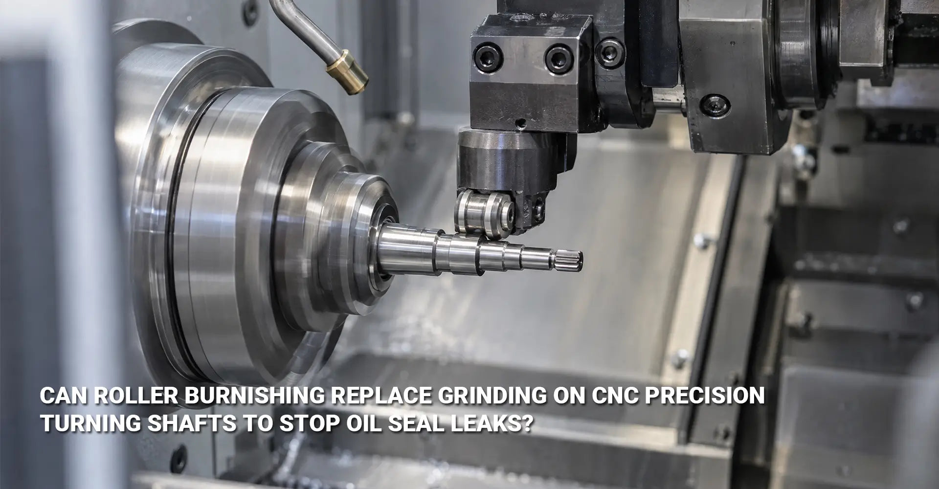
Burnishing is a cold-working step. Hardened rollers press on the turned surface, flatten the peaks, and push metal into the valleys. This closes shallow grooves and lowers Ra. Grinding, in contrast, removes material with an abrasive wheel and gives the tightest geometry. In short, burnishing is faster and often cheaper, while grinding is stronger for hard or very precise parts.
To compare the two routes fairly, look at three processes side by side:
| Process | Typical Ra | Main Strength | Main Watch-Out |
|---|---|---|---|
| Turning only | Often 0.8 µm or higher | Lowest cost | Lead marks remain, so leaks are likely |
| Turning + burnishing | About 0.1–0.4 µm | Done on the same lathe; closes micro-grooves | Needs a clean pre-turned surface; diameter shifts slightly |
| Turning + grinding | 0.2–0.4 µm or better | Best roundness and size control; works on hard steel | Extra setup, handling, and cost |
Let's go deeper into how burnishing works. The rollers deform the surface peaks under controlled pressure. Because the metal flows instead of being cut, the surface also gains a thin layer of compressive stress. This layer can help fatigue life. However, the process needs three things to work well:
- A good pre-turned surface. Burnishing smooths peaks, but it cannot fix deep chatter or tool damage.
- Proper lubrication. Without it, the rollers can scuff the surface.
- Controlled tool pressure. Too little pressure leaves peaks behind. Too much can flake the surface.
Material matters as well. Burnishing works well on low-carbon steel, medium-carbon steel, stainless steel, aluminum, and brass. In general, it suits materials up to about 45 HRC, depending on the roller and the settings. Harder shafts may need diamond burnishing or grinding. Always test the process on your real material and hardness before production.
Diameter also changes. Burnishing flattens peaks, so the finished diameter can shrink slightly. The change depends on the starting roughness and the pressure. For this reason, the program should leave the pre-turn diameter a little oversize. Then, the first article should confirm the final size against the seal interference limit.
Next, think about cost and lead time. Turning plus burnishing can run on one CNC lathe, so it skips a second setup. In some projects, this route costs 20–40% less than grinding. Even so, you should quote both routes to confirm the numbers for your own part.
Now, when can burnishing replace grinding? It is a good fit when:
- The material is below the hardness limit.
- The seal needs Ra 0.2–0.4 µm and no spiral lead.
- The tolerance is normal for a seal journal.
- The volume is high enough that a second operation adds real cost.
On the other hand, keep grinding when the shaft is very hard, the roundness limit is extremely tight, or the drawing calls for a ground finish.
When you buy custom CNC turned shafts, ask the supplier to quote both routes and explain the risk of each. Good precision shaft manufacturing also plans the pre-turn size, the burnishing pressure, and the inspection steps together. In production shaft machining, this matters even more, because small changes in tool wear can shift Ra and diameter from one batch to the next. Finally, any supplier that offers roller burnishing services should show before-and-after Ra data, not just a promise.
How Can an Oil Seal Leakage Test Prove the Shaft Will Not Leak?
"It looks smooth" is not an acceptance test. A smart buyer asks for proof. Otherwise, the first real test happens in the field, when a gearbox fails and the warranty claim arrives.
Ask for four proofs. Start with surface roughness measurement that reports Ra and Rz. Next, require a texture check for spiral lead. Then, request roundness and diameter data. Finally, ask for a grease leak test on first articles, followed by a quicker screening check on each batch.
Let's walk through each step.
Measure the surface. Use a profilometer and record Ra, Rz, and Rmax. Measure along the shaft axis, because lead marks run around the shaft. Also, take readings at several spots on the journal.
Check the texture. Visual inspection alone is not reliable. Instead, use magnification with low-angle light to look for directional grooves. For critical seals, ask the supplier for texture images taken before and after burnishing. The goal is a uniform, non-directional surface in the seal contact zone.
Measure shape and size. Check roundness with a roundness tester when possible. Then, check the diameter against the seal interference range. Because burnishing can shift the diameter, measure after the final pass.
Run the leak test. Use the real gearbox or a good seal fixture. The test should include:
- Rotation at operating speed
- Thermal cycling, if the gearbox heats up in service
- A long enough run to match real life, such as 200–1,000 hours or an accelerated version
- A final check for grease moving past the seal lip
Sample every batch. Test the first article in full. After that, use a shorter pressure decay or visual leak check for batches. Keep full durability tests for first articles and for any process change.
Next, put the rules into the paperwork. A clear drawing and purchase order should list:
- Material and hardness
- Journal diameter and tolerance
- Ra target, such as 0.2 or 0.4 µm, plus an Rz limit
- "No spiral lead at the seal contact area"
- Roundness or cylindricity limit
- Process route: turning plus burnishing, or turning plus grinding
- Inspection data: Ra, roundness, diameter, and texture images
- A first-article report and the leak test method
Then, ask your supplier a few direct questions:
- How do you control the pre-turn surface before burnishing?
- How do you adjust the diameter for the size change?
- What Ra and roundness data will you send with each lot?
- How do you check for spiral lead?
- Have you tested this journal with a real seal and grease?
Here is an illustrative example. A turned journal with spiral lead showed grease leakage after 200 hours. After burnishing, the same journal reached Ra 0.2 µm or lower and ran 1,000 hours with no leakage. In that case, the grease leakage dropped by about 70%. Please treat these numbers as an example only. Your results depend on your seal, grease, speed, and temperature, so run your own test.
Conclusion
A leaking gearbox does not always mean a bad seal. Very often, the shaft surface is the weak link. Turning marks, rough peaks, and poor roundness can pump grease out even when the shaft looks perfect. The good news is that you can control these risks with a clear drawing and simple proof.
In short, burnishing can replace grinding for many oil seal shafts. It works best when the material is within the hardness limit, the pre-turned surface is clean, and the result is checked. Grinding remains the right choice for very hard parts and very tight tolerances. The real winner is the route you can prove with data.
Here is your quick buying rule:
- Turn the shaft to a stable, clean pre-surface.
- Burnish it to close spiral lead and lower Ra, or grind it when the part demands it.
- Specify Ra 0.2–0.4 µm and no continuous spiral lead at the seal contact area.
- Hold roundness and diameter inside the seal limits.
- Require a first-article leak test and a batch screening method.
The difference between a leaking gearbox and a dry one is often a tiny turning groove that no one closed and no one checked. If you want a second set of eyes on your drawing, talk with our team about CNC machining services and a design review before you release the order.
Recommended External Resources
[Oil seal shaft surface finish][^3]
[Roller burnishing vs cylindrical grinding][^4]
[CNC turning surface texture][^5]
[^1]: INTEGI (Spain-based precision machining tool manufacturer) process validation case showing spherical ball joint burnishing on a MORI SEIKI NLX CNC lathe using a standard HBU burnishing tool. It provides specific process parameters—cutting speed Vc = 200 m/min, feed 0.025 mm/rev, burnishing interference 0.5 mm, spring compression force 160 N—and notes reduced surface roughness, eliminated micro-irregularities, and improved fatigue resistance without dedicated equipment.
[^2]: SolidCAM (Israel/global CAM software company) high-precision machining benchmark page providing practical CNC turning tolerance ranges from ±0.0005 in. to ±0.002 in., typical surface finishes from Ra 0.4 µm to Ra 3.2 µm, and typical applications such as shafts, bushings, pins, threads, and cylindrical features. It also lists key accuracy variables including workholding, spindle stability, insert geometry, and feed per revolution, and compares turning against milling, 5-axis, Swiss, and grinding benchmarks.
[^3]: Polypac (UK-based sealing solutions provider) publishes a practical, engineering-led guide to PTFE oil seal selection that directly addresses shaft surface finish requirements. The guide specifies that for dynamic PTFE sealing, the recommended shaft roughness is **Ra 0.2–0.8 µm (8–32 µin)** , explaining that too smooth a finish increases the risk of stick-slip while too rough accelerates abrasive wear. For reciprocating motion, it recommends finer finishes toward **0.2–0.4 µm Ra** as the best compromise between lubricant retention and wear. The page also notes that a common industry minimum hardness is **≥45 HRC** for rotating shafts, and advises defining surface finish and hardness tolerances on engineering drawings with verification via profilometer and Rockwell readings.