
Why Do Large-Diameter Threads on Underwater Camera Extension Ports Seize or Leak?
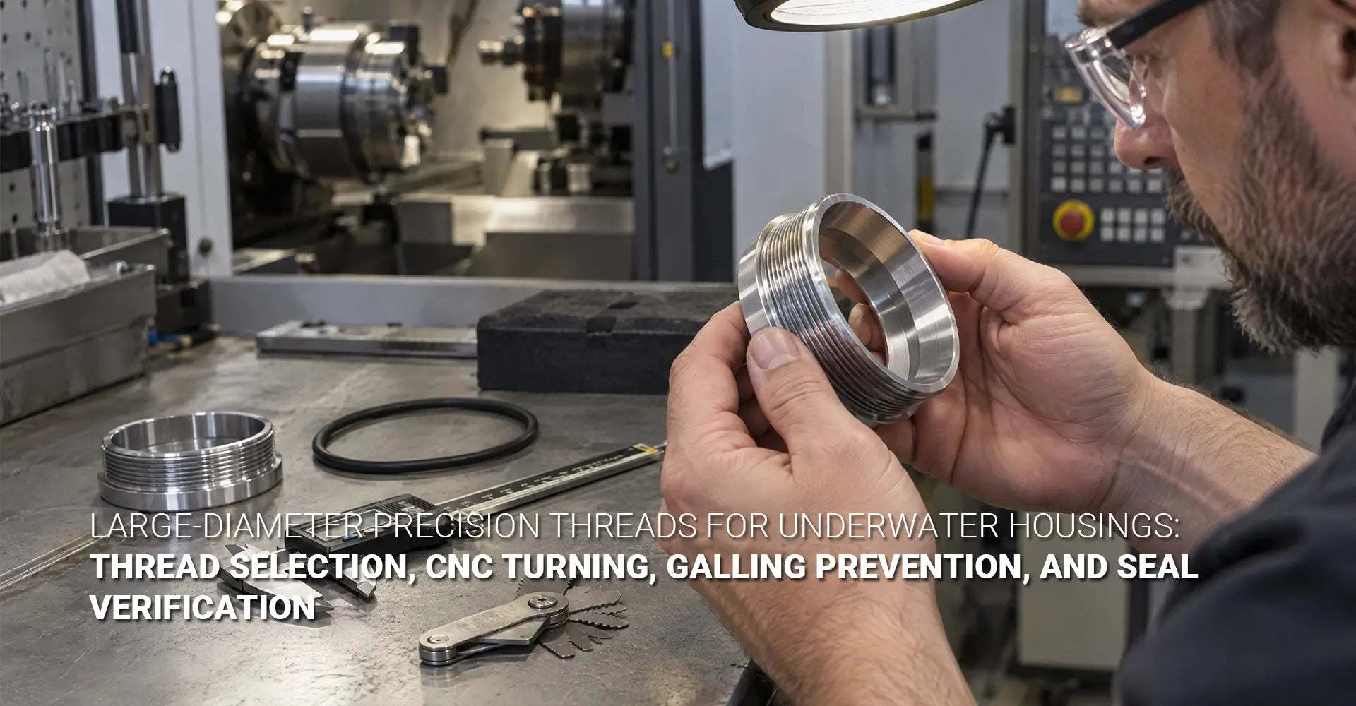
Why Do Large-Diameter Threads on Underwater Camera Extension Ports Seize or Leak?
A new port spins on smoothly in the shop. Then, after a few dives, it starts to bind, scrape, or let in water. For a buyer, this is a costly and frustrating surprise. In most cases, the thread is the cause, not the housing. A good underwater camera extension port needs a thread that turns smoothly and an O-ring that seals evenly. That balance starts with well-made CNC turning components and a clear plan for fit, finish, and testing. This guide shows procurement managers and engineers what to check before they place an order.

Large-diameter threads seize because of galling, which is metal sticking and tearing during assembly. They leak because the O-ring is squeezed unevenly, not because the thread is loose. The thread holds the port in place. The O-ring makes the seal. To fix both problems, design, machine, and test the thread and the seal as one system.
Quick Answers at a Glance
| Question | Short Answer |
|---|---|
| Why does the port seize? | Galling. Rough, tight, or dry threads rub and weld together. |
| Why does it leak? | The O-ring gets too little or uneven squeeze. |
| Which pitch works best? | Fine pitch for large ports, if tooling and inspection are good. |
| Which fit is a common start? | 6H/6g, then confirm with assembly testing. |
| What finish helps most? | Smooth thread flanks, Ra ≤ 0.8 µm. |
| How should you test it? | Test the full assembly at 1.5× rated depth for at least 30 minutes. |
| What is the main rule? | Threads hold. O-rings seal. |
Now that you have the short answer, let's look at the details. First, we will see why threaded ports fail. Next, we will compare thread choices. Then, we will cover how CNC turning holds tight tolerances. Finally, we will look at galling control, O-ring sealing, and testing. Each section ends with items you can add to your drawing or purchase order.
Table of Contents
- What Makes a Threaded Extension Port Seize or Leak?
- How Should You Choose the Thread for a Large-Diameter Port?
- How Does CNC Turning Hold Tight Tolerances on Large-Diameter Threads?
- How Can You Prevent Galling and Verify the O-Ring Seal?
- Conclusion
What Makes a Threaded Extension Port Seize or Leak?
Underwater cameras are delicate devices, so the housing must keep water out on every single dive. Teams that work in electronics manufacturing know that one small leak can ruin a whole unit. Many housings use a port extension ring to hold a lens or dome at the right distance. The ring screws into the underwater housing port, and that threaded joint takes the most abuse. As a result, users often report threads that bind, gall, or leak after repeated assembly.
A threaded port usually fails in one of three ways. First, galling makes the threads stick and tear. Second, poor axial location leaves the port sitting at the wrong depth. Third, the O-ring gets too much or too little squeeze. In short, thread fit alone does not make a waterproof seal.
Let's look at each failure mode in plain terms.
- Galling. Galling is a type of wear where two metal surfaces rub, stick, and tear. Material moves from one surface to the other. In the worst case, the threads cold-weld and lock together.
- Poor axial location. If the port does not seat against the housing face the right way, the O-ring sits off-center. As a result, the gap around the seal is uneven.
- Seal miscompression. If the port stops short, the O-ring gets squeezed too little. If it goes too far, the ring gets crushed. Both cases can cause leaks.
Large diameters make these problems worse. A bigger thread has more contact area. Therefore, it reacts more strongly to rough finish, tight clearance, and dirt. A small burr that you would never notice on a small thread can score a large one.
Key point: The thread provides mechanical retention. The O-ring provides the seal. Mixing up these two jobs is a common cause of leaks.
Also, a tight thread can still leak. Water does not need a big gap. It only needs a path. If the O-ring is not compressed evenly, water can slip past it, even when the thread feels firm by hand. For this reason, good design treats the thread, the groove, and the housing face as one linked system.
What to add to your purchase order:
- Name the three failure modes in your quality notes, so the supplier knows what to prevent.
- Ask for the thread, the O-ring groove, and the housing face to be reviewed together.
- Require repeated assembly testing, not just a one-time fit check.
How Should You Choose the Thread for a Large-Diameter Port?
Thread choice sets how the port feels in the hand. It also decides how well the port seats. A poor choice can cause trouble even when the machining is perfect. Therefore, pick the thread early, before the drawing is final.
Fine pitch threads are usually the better pick for big ports. They give smoother assembly and more precise axial adjustment. Coarse threads are stronger and handle dirt better, but they carry more galling risk. A 6H/6g fit is a common starting point. However, always confirm the fit by assembly testing.

Let's compare the two pitch types first.
| Feature | Coarse Pitch | Fine Pitch |
|---|---|---|
| Axial adjustment | Less precise | More precise |
| Vibration loosening | More likely | Less likely |
| Assembly feel | Can feel rough | Smoother when finished well |
| Dirt tolerance | Better | Lower |
| Galling risk | Higher | Lower when properly finished |
| Sensitivity to pitch diameter error | Lower | Higher |
| Tooling and inspection needs | Basic | Stricter |
As the table shows, fine pitch is not free of trade-offs. Fine pitch thread machining demands sharper tools, steadier setups, and tighter checks. A small error in pitch diameter has a bigger effect on a fine thread. So, only choose fine pitch if your supplier can measure it well.
Next, think about fit. The thread fit class tells the shop how much clearance to leave between the internal and external thread. A tighter fit reduces play, but it raises the galling risk. A looser fit assembles easily, but the port may rock and squeeze the O-ring unevenly. Pick the fit that gives smooth assembly without extra play. Then verify it with go/no-go gauges and a torque check.
Length matters too. Thread axial location describes where the port stops when it is fully tightened. A longer thread gives better alignment, yet it also adds more contact area and more friction. The goal is a port that seats on the housing face at the same depth every time. That repeatable depth is what gives the O-ring a steady squeeze.
Finally, decide between metric and imperial. Metric threads are common and easy to gauge. Imperial threads may match older housing designs or customer habits. In either case, confirm that your supplier has the right tools and gauges on hand. When you order large diameter precision threads, ask what gauges the shop uses and how often they are calibrated.
Buyer tip: Ask for a first article report on your precision threaded components. It should list pitch diameter, gauge results, and assembly torque. This one document tells you a lot about the supplier.
What to add to your purchase order:
- Thread size, pitch, and tolerance grade
- Thread length and the required seating depth
- A note that fit must be confirmed by assembly testing
How Does CNC Turning Hold Tight Tolerances on Large-Diameter Threads?
Large threads are harder to cut than small ones. The tool is longer, the cutting forces are higher, and small errors add up. Many buyers search for CNC single-point threading large diameter services for this reason. Still, the process is very capable when the shop controls a few key factors.
Single-point CNC turning can cut large threads with accurate pitch diameter, lead, and thread form. To get there, the shop needs rigid tooling, steady spindle and feed synchronization, and sharp inserts. In-process measurement then catches drift before it ruins a batch.
Here is what matters most on the machine.
Tool geometry. The tool tip width and angle must match the thread form. A worn or wrong tip leaves a thread that looks fine but assembles poorly. Therefore, the shop should use sharp inserts made for the exact thread profile.
Pitch synchronization. The lathe must link spindle rotation to tool travel with high accuracy. If this link drifts, the lead will be wrong. As a result, the port will bind as it turns.
Tool wear. As the insert wears, the thread gets thicker or thinner. This is called pitch diameter drift. On a large part, even a small drift can move the fit from smooth to tight. So, good shops check the thread every few parts and change inserts on a set schedule.
Start and runout details. A proper thread start chamfer helps the port enter straight, which prevents cross-threading. In addition, add a lead-in taper on the external thread and deburr the start of the thread. Cross-threading is often a design and machining issue, not just a user mistake.
Alignment with the seal. The thread must line up with the seal bore. Good thread concentricity keeps the port square to the housing. Because of this, the O-ring gets even pressure all the way around.
Measuring the result. Thread pitch diameter inspection should use more than one method. Go/no-go gauges check the specified fit. Thread micrometers or the three-wire method confirm the pitch diameter. For critical ports, a thread profile scanner or an optical comparator checks form, lead, and flank angle. Finally, the shop should record the results on the first article report.
Why it matters: Large threads are more sensitive to tool wear and machine alignment than small ones. For this reason, inspection is not optional. It is part of the process.
What to add to your purchase order:
- Single-point threading with pitch diameter and lead checks
- Start chamfer angle and length
- Concentricity requirement between the thread and the seal bore
- Gauge types and sampling plan
How Can You Prevent Galling and Verify the O-Ring Seal?
Galling and leaks often come from the same weak spots. These include a rough finish, leftover burrs, or uneven compression. Therefore, it makes sense to fix both problems together. The steps below cover surface, lubrication, sealing, and testing.
Thread galling prevention works best as a stack of small steps. Use a smooth finish (Ra ≤ 0.8 µm), enough clearance, a compatible lubricant, and careful deburring. Next, pressure test the full assembly at 1.5× the rated depth for at least 30 minutes. No single step is enough on its own.
Let's start with the cause of galling. Aluminum is soft and forms a thin oxide skin. When two aluminum threads rub under load, the skin breaks and fresh metal sticks together. If you want more background, see our guide to aluminum in CNC machining. One simple fix is to use different materials or different surface treatments on the two mating parts.
Surface treatment is the next step. Anodizing adds a hard oxide layer, and it grows both into and out of the surface. As a result, it changes thread size and roughness. Anodized thread galling is a real risk if the coating is not controlled. Hard aluminum anodizing gives strong wear resistance, yet it can chip on sharp thread edges. So, always check the thread fit after coating, not just before.
Coatings can help as well. Anti-seize coating aluminum threads, such as PTFE-based types, reduce friction and material transfer. However, the coating must be safe for the O-ring and the water environment. Ask your supplier to test the coating and the O-ring material together.
Next, think about lubrication. The right lubricant for threaded underwater housing use must be safe for aluminum and for the O-ring. Silicone-based and PTFE-based greases are common choices. Avoid products that swell the O-ring or leave residue on the seal. Apply a thin, even film. More grease is not better, because extra grease can trap dirt and block the seal.
Clean threads matter as much as the grease. Before assembly, remove chips, burrs, and old lubricant. A tiny metal chip in a fine thread can start a gall in seconds. Therefore, write cleaning and deburring steps into the work instruction.
Now let's turn to the seal. The O-ring seal threaded port is a separate design from the thread itself. There are two common types:
- Radial seal. The O-ring is squeezed against the side of the bore. It is forgiving about small changes in port depth.
- Face seal. The O-ring is squeezed against the housing face. It depends more on a steady seating depth, so axial location must be tight.
For both types, the groove size and finish are key. A static O-ring seal usually works well with about 15% to 30% squeeze. If the groove is too deep, the ring is loose. If it is too shallow, the ring is crushed. In addition, the groove walls should be smooth, with no tool marks or burrs. Also, keep the groove concentric to the thread, so the squeeze stays even all the way around.
Finally, prove the design with a test. A Pressure test threaded port check should include the whole assembly: the housing, the port, the O-ring, and the thread. For a 100 m rating, test at 1.5× depth, which is about 150 m equivalent. Hold the pressure for at least 30 minutes and look for leaks. Then, check that the port still turns smoothly after pressure cycling. Record the test pressure, the hold time, the result, and any change in assembly torque.
Remember: A port that seizes or leaks is usually the result of thread design, machining, and sealing being treated as three separate jobs. Treat them as one system.
Supplier checklist for your purchase order:
- Thread pitch, fit, and length, with a note to confirm by assembly testing
- Material, surface treatment, and coating, with fit checked after coating
- Thread flank finish of Ra ≤ 0.8 µm and deburred start and runout areas
- Approved lubricant that is safe for aluminum and the O-ring
- Groove dimensions, finish, and concentricity to the thread
- Pressure test records for the full assembly
- First article report with gauge results and assembly torque
Conclusion
A threaded port does not have to seize or leak. Most failures come from a few clear causes. The thread was chosen without thinking about galling. The machining was not checked well enough. Or the O-ring did not get an even squeeze. Each of these can be fixed with a clear specification and good inspection.
To sum up, remember these main points:
- Do not treat threads as a seal. The thread holds the port. The O-ring seals it.
- Choose the thread with care. Fine pitch often works best on large ports, but it needs better tooling and inspection.
- Control the machining. Single-point CNC turning with pitch diameter and lead checks gives repeatable results.
- Prevent galling. Combine finish, coating, clearance, lubricant, and deburring.
- Verify the seal. Test the full assembly and record the results.
When you source CNC threaded aluminum parts, ask for a first article report and the test data before volume production starts. These simple records show whether the supplier has control of the process. If you want a second opinion on your drawing, our team can review the thread, groove, and seal with you. Learn more about our CNC machining service or send us your drawing for a design review.
Recommended External Resources
[large diameter precision threads][^1]
[CNC threaded aluminum parts][^2]
[Fine pitch thread machining][^3]
[Thread galling prevention][^4]
[underwater camera extension port][^5]
[^5]: HousingCamera.com (US-based underwater photography retailer and resource) publishes a comprehensive 2026 guide explaining underwater camera ports in full. It covers the optical principles of flat versus dome ports, how refraction changes the field of view underwater, and the specific role of extension rings in positioning the lens correctly behind the dome to maintain sharpness and corner quality. The guide also explains how to read port charts to select the exact extension ring combination for a given camera, housing, and lens—directly addressing the engineering and compatibility questions around underwater camera extension ports.
[^6]: USDV (US-based vision measurement system manufacturer) provides a detailed technical application page on thread concentricity measurement for precision screw components. It explains that concentricity between the thread axis and the screw head directly influences locking stability and durability, and notes that traditional mechanical methods like concentricity meters or dial gauges suffer from inaccurate clamping and probe instability on curved thread surfaces. The page presents the TIMI-series non-contact image measurement system as an alternative, achieving a thread concentricity measurement precision of ±0.01 mm with a 5–10 second cycle time, making it a directly relevant resource for thread concentricity inspection methodology and equipment.