Why Does Your Stainless Steel 3D Printed Base Warp the Moment You Remove It From the Plate?
Why Does Your Stainless Steel 3D Printed Base Warp the Moment You Remove It From the Plate?
You just finished a long print job. The part looks perfect while it sits on the build plate. Then you cut it free, and it bends. This frustrating problem affects many teams who rely on precision 3D printing for large, flat stainless steel parts. The good news is that this warping is not random. It follows clear physical rules, and those rules can be managed.

A stainless steel part warps after removal because the build plate holds it straight against forces trapped inside the metal. During printing, fast heating and cooling create stress inside each layer. This is called selective laser melting residual stress, and it builds up layer by layer as the metal heats and cools. Once you remove the part, that trapped stress finds a new balance, and the part bends.
So how do you stop this from happening to your parts? The fix is not one single trick. It comes from three connected steps working together. First, engineers manage the heat during the print. Next, they use special supports to hold down stress points. Finally, they heat-treat the finished part to release what stress remains. Let's walk through each step below.
Table of Contents
- Why Does a Perfectly Straight Part Bow the Moment It Leaves the Build Plate?
- What Is Thermal Balancing, and Can It Really Reduce Warping?
- How Do Anchor Supports Prevent Distortion Instead of Just Holding Parts Up?
- Why Is Stress Relief Annealing a Required Step, Not an Optional One?
Why Does a Perfectly Straight Part Bow the Moment It Leaves the Build Plate?
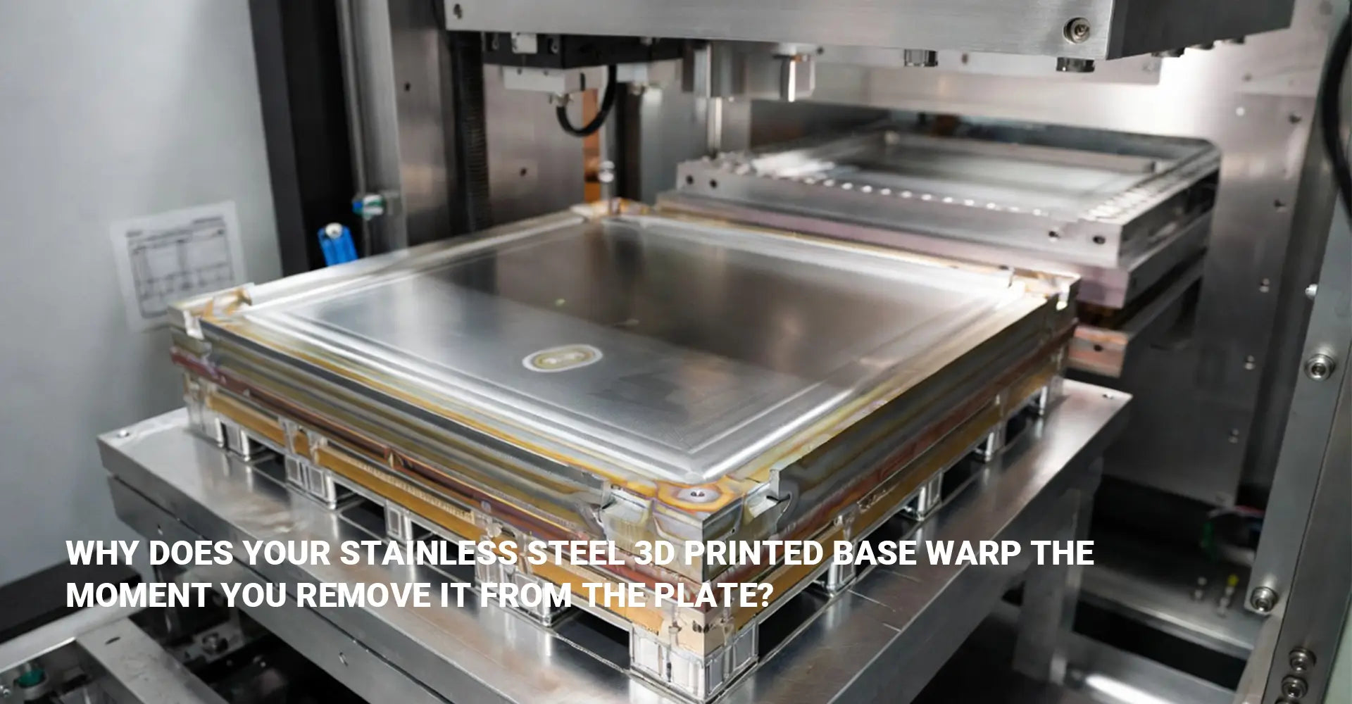
Picture a large, flat stainless steel base coming off the printer. It sits on the build plate looking flawless. Then a technician cuts it away with a wire EDM or band saw. Within minutes, the once-flat surface curves upward at the edges. This is not a rare accident. It happens because of forces that were present the entire time.
The build plate acts like a clamp. It holds the part flat while thermal gradient distortion builds up inside the metal, layer after layer. Once that clamp is gone, the stored stress pulls the part out of shape.
Selective laser melting uses a laser to melt thin layers of metal powder. Each layer heats and cools at rates near 1,000 Kelvin per second. That speed locks stress into the metal before it has time to relax. Large, flat geometries suffer the most because they cover a wide area with an uneven stress spread. One edge may cool faster than the center, and that mismatch creates bending force. Studies using synchrotron X-ray diffraction have measured compressive residual stress in as-printed 316L stainless steel at around −197.4 MPa. That number shows how much force sits inside the part, waiting to be released. Strong build plate adhesion keeps the part anchored while this stress builds, but adhesion alone cannot fix the problem once the part is finally cut free.
What Is Thermal Balancing, and Can It Really Reduce Warping?
Thermal balancing is the first tool engineers reach for. The idea is simple: shrink the temperature gap between the hot melt zone and the surrounding metal. A smaller gap means less stress builds up in the first place.
Thermal balancing works mainly through substrate preheating SLM, where the build plate is heated before printing starts. This step narrows the temperature difference between new and old layers.
Most shops preheat the build platform to between 150°C and 200°C for 316L stainless steel. This warmer starting point slows the cooling rate of each new layer. Slower cooling gives the metal more time to relax through small amounts of bending, instead of locking in stress. For parts with a history of severe distortion, some advanced machines raise the whole chamber temperature up to 500°C. This extra step costs more, but it can save a large or expensive part from failing. Manufacturers who offer full-service metal 3D printing typically build preheating controls into their standard process rather than treating it as an upgrade.
How Do Anchor Supports Prevent Distortion Instead of Just Holding Parts Up?
In plastic printing, supports hold up overhangs so they don't sag. Metal printing works differently. Anchor supports SLM serve a different job: they hold the part down, not up.
These supports resist the pulling force of residual stress. They also pull heat away from hot spots, acting like small heat sinks built right into the design.
The best practice is to attach supports early, right into the base of the part, especially near areas prone to heavy deformation. A common mistake is placing isolated, stand-alone supports in trouble spots. This seems logical, but it often makes warping worse. Isolated supports add extra pulling forces of their own, which can cause buckling instead of preventing it. Engineers now use simulation software, such as ANSYS Additive Suite or Simufact Additive, to predict where a part will warp before it ever gets printed. This lets them design supports that spread the load evenly across the base. Teams building pump housings and other prototype parts through rapid prototyping services rely on this simulation step to avoid costly reprints.
Why Is Stress Relief Annealing a Required Step, Not an Optional One?
Even with perfect preheating and smart supports, some stress remains after printing. Stress relief annealing metal 3D printing is the final step that removes most of what is left.
For 316L warping control, the proven annealing range sits between 400°C and 650°C, held for about two hours. This range relieves stress without badly hurting the metal's strength.
Research shows moderate to full stress relief of about 24%, 65%, and roughly 90% after two-hour annealing at 400°C, 650°C, and full solution annealing at 1,100°C for five minutes. But higher heat brings a trade-off. Embrittling phases can form between 650°C and 800°C, and that lowers ductility. For large, flat bases that need the dimensional stability additively manufactured parts require, the 400°C to 650°C range for two hours is the safe sweet spot. Vacuum stress relief is strongly preferred over open-air annealing, since it stops surface oxidation from forming during the heat cycle. This same treatment also softens the metal slightly and improves ductility, because dislocations inside the structure rearrange and relax during the process. For most industrial pump bases, this small strength trade-off is worth the gain in flatness. Buyers who want proof of this process should ask their supplier about post-anneal inspection, which is typically covered under a proper quality assurance program.
Conclusion-What Should You Require From Your Metal 3D Printing Supplier?
SLM stainless steel warping is not bad luck. It is physics, and physics can be managed. If you order a large, flat 316L base, ask your supplier for four things in writing: preheating of the build plate to 150°C–200°C, computer simulation of support placement, anchor supports connected early to the part, and stress relief annealing at 400°C–650°C for two hours in a vacuum or inert atmosphere. Ask them to follow up with a CMM or optical scan after annealing to confirm the final shape.
A supplier who controls this full thermal chain can hold tolerances as tight as ±0.05mm on heavy-duty pump bases used across industrial machinery applications. A supplier who skips these steps will hand you a part that bends, and the cost of scrapping or reworking that part will always outweigh the cost of doing it right the first time. This same discipline matters whether your project needs metal or plastic 3D printed parts, since thermal planning still affects warp-prone geometries either way. As one research review noted, a controlled stress relief treatment before a part goes into service gives predictable stress levels, stable structure, and stronger long-term performance.
Procurement Checklist: What to Require From Your Metal 3D Printing Supplier
Preheat — Build platform preheated to 150°C–200°C minimum for 316L stainless steel (up to 500°C chamber temperature for stress-prone geometries)
Simulate — Warping simulation performed before printing, with support layout optimized using tools like ANSYS Additive Suite or Simufact Additive
Anchor Supports — Supports attached early into the part geometry near high-deformation zones, not placed as isolated stand-alone supports
Anneal + Inspect — Stress relief annealing at 400°C–650°C for 2 hours in vacuum or inert atmosphere, followed by post-anneal dimensional inspection via CMM or optical scanning
A supplier who checks all four boxes can consistently hold tight tolerances on large, flat stainless steel bases. A supplier who skips even one step is a warping risk. The cost of scrapping or reworking a warped part — lost material, missed deadlines, re-machining fees — will almost always exceed the cost of proper thermal management done right the first time.
Recommended External References:
[SLM stainless steel warping][^2]
[selective laser melting residual stress][^3]
[stress relief annealing metal 3D printing][^4]
[thermal gradient distortion][^5]
[^1]: A comprehensive guide from Raise3D that defines dimensional accuracy, precision, and repeatability in 3D printing, with practical tips for achieving tight tolerances and high-quality output[reference:0][reference:1].
[^2]: A peer-reviewed academic study from The International Journal of Advanced Manufacturing Technology investigating warpage and dross formation in curved overhanging structures fabricated from 316-L stainless steel via SLM, with analysis of energy input and obliquity angle effects[reference:2][reference:3].
[^6]: An open-access original paper from Springer that systematically classifies SLM support structures into sheet-like and rod-shaped types, comparing their effects on horizontal overhang fabrication through finite element simulation and experiments, demonstrating that sheet-like supports reduce maximum deformation to 13.5 μm versus 30.7 μm for rod-shaped supports due to superior thermal conductivity and structural rigidity.[reference:2][reference:3]