Why Does Poor Chip Evacuation Cause CNC Overheating and Tool Damage?
Why Does Poor Chip Evacuation Cause CNC Overheating and Tool Damage?

Quick Answer: Chip Color Temperature Guide
| Chip Color | Temperature Status | Action Required |
|---|---|---|
| Silver/Tan | Normal (300-400°F) | Continue current settings |
| Light Blue | Warning (500-600°F) | Review speeds and feeds |
| Dark Blue/Purple | Critical (700°F+) | Stop and adjust immediately |
| Black/Burnt | Extreme Damage | Tool replacement needed |
When you notice burnt chips, rough surface finishes, or tools failing faster than expected, the problem often starts with one thing: poor chip evacuation. In fact, studies show that inadequate chip removal reduces tool life by up to 70% and creates thermal damage that spreads throughout your workpiece.
Poor chip evacuation is the silent killer of CNC productivity. When chips aren't cleared properly, they get recut by the tool, generating exponential heat that damages both your equipment and workpiece. This guide reveals exactly why chip buildup causes overheating, what signs to watch for, and how to fix these problems without expensive equipment upgrades. Additionally, we'll share proven strategies from professional machinists who've solved these challenges in real production environments.
You'll discover the direct connection between chip evacuation failures and thermal damage. Moreover, you'll learn practical solutions for deep cavity machining, compressed air techniques, and tool geometry adjustments. By the end, you'll have a complete action plan to prevent CNC overheating problems and extend tool life significantly.
Now that you understand why chip control matters, let's explore the mechanical reasons behind overheating and the specific damage patterns you need to recognize.
Table of Contents
- What Happens When Chips Aren't Removed Properly During CNC Milling?
- How Can You Fix Chip Evacuation Problems in Deep Cavity Machining?
- Which Chip Removal Method Works Best: Compressed Air or Coolant?
- What Tool Geometry Changes Improve Chip Flow and Reduce Heat Buildup?
- Conclusion
What Happens When Chips Aren't Removed Properly During CNC Milling?
When chips remain in the cutting zone, they create a vicious cycle of heat generation and tool damage. Consequently, your cutting tool encounters the same metal chips multiple times, effectively cutting them over and over again.
The Core Problem
Recutting chips is the primary cause of thermal damage in CNC milling operations. When CNC milling chip evacuation fails, the tool tip repeatedly cuts previously removed material. This generates exponential heat that weakens the tool substrate and leads to premature failure. Furthermore, this excessive heat causes work hardening in materials like stainless steel and titanium, making them even harder to machine.

Understanding the Damage Chain
The thermal damage process follows a predictable pattern. First, chips pack into the flute spaces of your end mill. Then, those packed chips get recut, creating intense friction and heat. As a result, several critical problems emerge:
- Tool substrate weakening - The carbide or high-speed steel loses its hardness and edge retention
- Thermal cracking - Rapid temperature changes create microscopic cracks in cutting edges
- Workpiece welding - Hot chips literally weld themselves to your finished surface
- Dimensional errors - Heat expansion changes part dimensions during cutting
Professional machinists report that "When we see blue chips, we know our chip evacuation has failed." This color change indicates temperatures exceeding 600°F, which is well beyond safe cutting parameters. In addition, these high temperatures destroy the surface finish quality you've worked hard to achieve.
Recognizing the Warning Signs
You can identify chip evacuation failures before catastrophic damage occurs. Watch for these symptoms:
Immediate indicators include discolored chips (purple or blue), unusual cutting sounds, and increased spindle load. Similarly, you might notice stringy chips that wrap around the tool holder instead of breaking cleanly. Longer-term signs include shortened tool life, inconsistent surface finishes, and parts that fail dimensional inspection.
Understanding these mechanisms helps you address problems before they escalate. Therefore, the next section explores specific solutions for challenging machining scenarios.
How Can You Fix Chip Evacuation Problems in Deep Cavity Machining?
The Deep Cavity Challenge
Deep pockets and cavities present unique chip evacuation challenges because chips must travel long distances to exit the cut zone. As a result, chips often pack tightly in confined spaces, creating the exact recutting problems we discussed earlier.
Proven Solutions for Deep Work
For deep cavity operations, you need systematic chip evacuation strategies CNC programmers have refined over years of production work. The following methods deliver measurable improvements in tool life and part quality:
Strategy One: Peck Milling Cycles
Peck milling involves programmed retract moves that break the cutting action and allow chips to clear. Specifically, your CNC program retracts the tool every 0.5 to 1.0 inches of depth. While this adds roughly 10% to cycle time, it typically doubles tool life by preventing chip packing. Experienced machinists emphasize that "For deep pocket work in steel, we program a full retract every 0.5 inches of depth to blow out chips."
Strategy Two: Toolpath Direction Matters
The direction your tool travels dramatically affects where chips go. Climb milling naturally throws chips forward, away from the cutting zone. Therefore, program your toolpaths to always push chips toward the cavity opening rather than deeper into corners. Additionally, avoid sharp 90-degree corners where chips naturally pack together.
Strategy Three: Shorter Tool Selection
Using shorter flute length end mills provides two benefits. First, shorter tools offer increased rigidity that reduces vibration and chatter. Second, they create less flute space where chips can pack. Consequently, chips evacuate more readily even in confined spaces.
Low-Cost Improvements That Work
You don't need expensive equipment upgrades to solve many chip evacuation problems. Instead, try these budget-friendly approaches:
- Increase compressed air blast pressure with a dedicated nozzle aimed directly at the cutting zone
- Modify your stepover percentage to create thinner, more manageable chips that flow better
- Add chip break cycles in your G-code for long engagements in difficult materials
- Use vortex tubes to convert regular compressed air into cold air for additional cooling effect
These CNC chip jam solutions cost little to implement yet deliver significant results. Moreover, they work across different industrial machinery configurations without major modifications.
Through-Tool Coolant Consideration
If your machine offers through-tool coolant capability, this becomes your most powerful chip evacuation tool. The pressurized coolant flows through internal channels in the tool body, forcing chips upward and out of deep cavities. While this requires compatible tooling, the improvement in chip removal CNC machining operations justifies the investment for production work.
Which Chip Removal Method Works Best: Compressed Air or Coolant?
Comparing Your Options
Choosing between compressed air and coolant isn't always straightforward because each method offers distinct advantages. Furthermore, the best choice often depends on your specific material, tool, and cutting parameters.
Compressed Air Advantages
Compressed air provides excellent chip clearing without the mess and maintenance requirements of coolant systems. Specifically, air blast works exceptionally well for:

- Aluminum machining where chips tend to be stringy and create "birdnests"
- Dry cutting operations where coolant would contaminate the workpiece
- Light cuts in plastics and other CNC metals and plastics
- Quick setup jobs where coolant mixing and cleanup adds unnecessary time
However, compressed air alone doesn't provide the cooling effect that flood coolant delivers. Therefore, air works best when cutting speeds are moderate and heat generation remains manageable.
Vortex Tube Technology
An innovative solution combines compressed air benefits with cooling capability. Vortex tubes split compressed air into hot and cold streams, directing the cold air at your cutting zone. This creates chip evacuation plus temperature reduction without liquid coolant mess. In addition, vortex tube systems cost less than $200 and install quickly on most machines.
Coolant System Benefits
Flood coolant or high-pressure coolant systems provide both chip evacuation and critical cooling. Consequently, coolant becomes essential for:
- Ferrous materials (steel, stainless steel, cast iron) that generate substantial heat
- High-speed operations where cutting temperatures exceed 500°F
- Difficult materials like titanium and Inconel that work-harden easily
- Long production runs where consistent temperature control maintains tight tolerances
The key factor with coolant is pressure and flow rate, not just volume. High-pressure coolant (1000+ PSI) physically blasts chips away while simultaneously cooling the cutting edge. Moreover, proper coolant flow CNC milling setups ensure the liquid reaches the exact cutting point rather than flooding the general area.
Material-Specific Recommendations
Different materials respond better to specific chip removal methods:
| Material | Best Method | Reason |
|---|---|---|
| Aluminum | Compressed air + mist | Prevents chip welding, reduces cleanup |
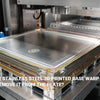
| Mild Steel | Flood coolant | High heat generation needs cooling |
| Stainless Steel | High-pressure coolant | Prevents work hardening |
| Titanium | Through-tool coolant | Critical temperature control |
| Plastics | Compressed air | Prevents material softening |
Hybrid Approaches Work Best
Many successful shops combine methods for optimal results. For example, they use flood coolant for primary cooling while adding directed air blast for specific chip clearing. This hybrid approach addresses both CNC machining heat issues and mechanical chip removal needs simultaneously.
What Tool Geometry Changes Improve Chip Flow and Reduce Heat Buildup?
Tool Design Impact
Your cutting tool's physical geometry directly determines how efficiently chips form and evacuate. Therefore, understanding these design elements helps you select tools that naturally prevent chip-related problems.
Flute Count Considerations
The number of flutes on your end mill creates a fundamental trade-off. Fewer flutes provide more chip clearance space, which becomes critical for CNC milling cooling solutions. Specifically:
- 2-flute tools offer maximum chip space, ideal for aluminum and deep slotting
- 3-flute tools balance chip clearance with surface finish quality
- 4-flute tools create excellent finishes but require perfect chip evacuation
- 5+ flute tools work only in finishing operations with minimal material removal
Professional machinists solved aluminum chip-birdnesting issues by "switching to a 3-flute end mill and increasing air blast pressure. The chips now fly clear of the cut zone." This simple change eliminated hours of machine downtime.
Helix Angle Effects
The helix angle determines how aggressively your tool throws chips upward and out of the cut. Higher helix angles (45-60 degrees) create stronger upward chip ejection forces. Consequently, tools with steeper helixes naturally prevent chip packing in deep cuts. However, remember that higher helix angles also create more axial cutting forces, which may affect thin-walled parts.
Chip Breaker Geometry
Modern cutting inserts feature engineered chip breaker designs that control chip formation. These small ridges and steps on the insert face force chips to curl and break into manageable segments. As a result, instead of long stringy chips, you get short C-shaped or comma-shaped chips that evacuate easily. This geometry proves essential for high-speed CNC milling overheating prevention.
Coating Selection Matters
Tool coatings do more than extend wear life. Specifically, certain coatings reduce friction between the chip and tool surface. TiAlN (Titanium Aluminum Nitride) coatings work excellently for CNC machining thermal management because they maintain hardness at high temperatures. Similarly, TiCN (Titanium Carbo-Nitride) coatings offer low friction properties that help chips slide away cleanly.
Rake Angle Influence
The rake angle (how the cutting edge meets the material) affects chip thickness and formation. Positive rake angles create thinner chips that require less cutting force and evacuate more easily. Therefore, when chip evacuation challenges exist, choose tools with positive rake geometry whenever material strength allows.
Practical Tool Selection Guide
When selecting tools specifically for better chip evacuation, prioritize these features:
- Choose one fewer flute than you typically use for that operation
- Select 45-degree or higher helix angles for deep cuts
- Specify variable helix geometry to break up harmonic vibrations that affect chip formation
- Request chip breaker inserts for turning and boring operations
- Use coated tools even for softer materials to reduce friction
These geometry changes work together with proper programming and coolant delivery to solve even stubborn chip evacuation problems. Furthermore, they provide long-term solutions rather than temporary fixes.
Conclusion
Bringing It All Together
Poor chip evacuation creates a cascade of problems that ultimately destroy tool life, ruin surface finishes, and waste production time. However, you now understand the root causes and practical solutions. Specifically, you've learned that chip recutting generates exponential heat, that different materials require specific evacuation approaches, and that tool geometry plays a critical role in chip formation.
Your Action Plan
Start by auditing your current chip evacuation performance. Look for the warning signs: discolored chips, poor finishes, and shortened tool life. Then, implement the low-cost solutions first—adjust your toolpaths for better chip direction, increase air blast pressure, and add retract moves to your programs. These changes cost nothing but deliver immediate improvements.
Next, evaluate your tool selection. Consider switching to fewer flutes, higher helix angles, and proper coatings for your specific materials. Remember that the right tool geometry naturally prevents chip packing without requiring constant intervention.
Finally, match your chip removal method to your material and operation. Use compressed air for aluminum and light cuts, but don't hesitate to implement high-pressure coolant for ferrous materials and difficult alloys. The investment in proper chip evacuation pays for itself through extended tool life and reduced scrap rates.
Recommended Reading
[CNC milling chip evacuation][^1]
[CNC milling cooling solutions][^2]
[chip removal CNC machining][^3]
[CNC chip jam solutions][^4]
[coolant flow CNC milling][^5]
[chip evacuation strategies CNC][^6]
---
[^1]: Explore this link to discover effective techniques for chip evacuation that enhance machining efficiency and tool life.
[^2]: Check out this resource to learn about innovative cooling solutions that can improve performance and reduce tool wear in CNC milling.
[^3]: Understanding chip removal techniques can enhance machining efficiency and product quality.
[^4]: Exploring solutions for chip jams can help prevent downtime and improve operational efficiency.
[^5]: Understanding coolant flow is crucial for optimizing machining performance and tool life. Explore this link to enhance your CNC milling knowledge.
[^6]: Effective chip evacuation is vital for maintaining precision and preventing tool damage. Discover strategies that can improve your CNC operations.


