One Crash, One Week Down: How Do You Audit a Supplier's 5-Axis CNC Milling Parts Fixture Clearance and Collision Simulation?
One Crash, One Week Down: How Do You Audit a Supplier's 5-Axis CNC Milling Parts Fixture Clearance and Collision Simulation?
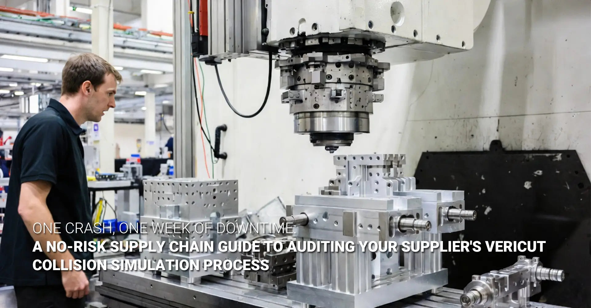
A machinist posted on Reddit: "Only 2mm of fixture clearance — how am I supposed to run this?" The replies flooded in. Every experienced operator recognized the problem immediately. But here is the part that matters to you as a procurement manager: that operator's frustration is your delivery schedule at risk.

When a supplier's fixture blocks the spindle path on a 5-axis machine, two things can happen. The machine throws an alarm and stops. Or the spindle physically crashes. Either way, your parts are not shipping on time. Understanding 5 axis cnc milling parts fixture clearance — and how to verify your supplier is managing it — is one of the most high-leverage procurement skills you can build.
Most buyers focus on price and lead time when sourcing complex machined parts. However, the real risk sits upstream: in the supplier's workholding setup and simulation workflow. A supplier who skips proper collision simulation is not saving time. They are borrowing it from your delivery schedule.
Table of Contents
- When the Spindle Tilts, Does Your Supplier's Fixture Get Out of the Way?
- Why Is 5-Axis Workholding Harder to Get Right Than 3-Axis?
- What Does a Real Collision Simulation Report Look Like for 5-Axis CNC Milling Parts?
- How Do You Audit a Supplier's Fixture Clearance and Simulation Workflow Before Awarding the PO?
When the Spindle Tilts, Does Your Supplier's Fixture Get Out of the Way?
A 5-axis machine looks like a standard machining center — until it starts moving. The moment the rotary axes engage, the spindle housing, tool holder, and tool trace a wide sweeping arc. That arc needs space. If a fixture is in the way, something breaks.
What happens when clearance fails:
- The machine detects a near-collision and triggers an emergency stop (alarm)
- The operator spends hours manually editing the program to find safe paths
- In worse cases, the spindle physically contacts the fixture — this is a crash
"A fixture that looks fine on screen can become a collision hazard the instant the table tilts to a compound angle."
The two outcomes — machine alarms vs. physical collisions — carry very different costs. Alarms interrupt production and add hours. Physical crashes can damage the spindle, destroy tooling, and stop the entire machine for five to seven days while repairs are completed. Both outcomes share the same root cause: workholding interference that was never caught before the program ran on the machine.
This is not an edge case. It is a recurring failure pattern in shops that treat fixture design as an afterthought. When a spindle tilts from 0° to 45° during a compound move, the tool holder sweeps through an arc that can be 50–80mm wide. A fixture clamp that sits just outside the tool diameter can still intersect that arc. Operators who discover this mid-cycle face a hard choice: stop the job and redesign the fixture, or try to manually jog around it. Neither option is cheap. Neither option is your problem to solve — but both become your problem when the shipment is late.
Why Is 5-Axis Workholding Harder to Get Right Than 3-Axis?
In 3-axis machining, the fixture does one job: hold the part still. The spindle only moves in X, Y, and Z. The fixture can be large, tall, and aggressive — because it never has to share space with a moving spindle housing. That simplicity disappears completely in 5-axis.
The core difference:
| Factor | 3-Axis | 5-Axis |
|---|---|---|
| Spindle movement | Linear only (X, Y, Z) | Linear + rotary (A/B/C axes) |
| Fixture risk | Minimal | High — fixture must clear all tilt angles |
| Clearance planning | Basic | Simulation-dependent |
| Crash potential | Low | High without proper modeling |
The 5-axis work envelope is not a fixed box. It shrinks as the table tilts. When the rotary axis moves to 30° or 45°, the spindle housing occupies more of the available space. A fixture that fits perfectly at 0° can protrude directly into the spindle's path at 30°.
Small parts on large tables create a counterintuitive trap. The workpiece sits near the table center. The table edge and fixture body extend outward. As the table tilts, those outer elements sweep upward — directly toward the spindle housing. This is especially common in automotive components and industrial machinery parts where complex geometry requires aggressive tilt angles.
There is also an important distinction between 3+2 positioning and full simultaneous 5-axis. In 3+2, the table indexes to a fixed angle and holds there. Clearance only needs to be verified at those discrete positions. In full simultaneous motion, the spindle and table move together continuously. A fixture that clears at 0° and 90° may still collide at 47° — because the spindle sweeps through every angle in between. Fixture design for 5-axis simultaneous work is significantly more demanding than fixture design for indexed positioning. Suppliers who only verify discrete positions are leaving the continuous path unchecked.
What Does a Real Collision Simulation Report Look Like for 5-Axis CNC Milling Parts?
"We ran simulation and it was fine." You have probably heard this. It sounds reassuring. It is not — unless you know what was actually simulated. There is a critical difference between toolpath verification and full machine simulation, and that difference determines whether your parts ship on time or sit in a queue behind a damaged spindle.
Toolpath verification checks whether the cutting tool collides with the part geometry. It is a CAM-level check. It is useful, but it is incomplete. It does not model the tool holder. It does not model the fixture. It does not model the spindle housing or the machine structure. A toolpath can be geometrically clean and still crash the machine.
Full machine simulation — using platforms like Vericut machine simulation — models everything:
- ✅ The full machine model (spindle, rotary axes, table, machine structure)
- ✅ The complete tool assembly (holder, collet, extension, shrink-fit components)
- ✅ The fixture and all workholding elements (vises, clamps, risers, custom plates)
- ✅ The raw stock material at every stage of material removal
Collision avoidance simulation at this level catches what CAM verification misses. It catches the tool holder hitting a fixture clamp at a 38° tilt. It catches the spindle housing grazing the workpiece edge during a simultaneous move. It catches axis travel limit violations that would trigger a hard fault on the machine. Digital twin machining — where a complete virtual replica of the machine, tooling, and workholding runs the program before any metal is cut — is the standard you should expect from a capable 5-axis supplier.
A credible simulation report includes:
- Screenshots or video of the full machine simulation — not just the toolpath render
- Clearance measurements — the minimum gap between all moving components throughout the entire cycle
- Collision log — a list of identified near-misses and how each was resolved
- Axis limit verification — proof that no movement exceeds the machine's travel limits
Clearance benchmark: 2mm is a red flag. 5–10mm is a working minimum. 15–20mm is a safe margin for production runs.
If a supplier cannot produce this documentation, they may not have run full simulation at all. They may have run CAM verification, called it "simulation," and moved on. For CNC machining services that involve complex 5-axis geometry, this distinction is the difference between on-time delivery and a week-long production stop.
How Do You Audit a Supplier's Fixture Clearance and Simulation Workflow Before Awarding the PO?
Procurement managers do not need to understand G-code. You do not need to read a simulation report yourself. You need to ask the right questions — and know what a confident, detailed answer looks like versus a hedge.
Here is your supplier audit checklist for 5-axis fixture clearance and collision simulation:
Question 1: What simulation software do you use — and do you model the full machine or just the toolpath?
✅ Strong answer: Names a specific platform (Vericut, CGTech, NCSIMUL, Mastercam Machine Simulation). Confirms the fixture, tool assembly, and machine structure are all modeled.
🚩 Weak answer: "We use our CAM software's built-in verification." This is toolpath verification, not machine simulation.
Question 2: Can you show me a digital twin simulation for a similar part you've run?
✅ Strong answer: Provides video or screenshots of full machine simulation, with visible fixture, tool holder, and machine body.
🚩 Weak answer: Shows only a CAM toolpath animation with no machine body visible.
Question 3: What is your minimum programmed clearance between the tool holder and fixture during aggressive tilt moves?
✅ Strong answer: States a specific number (e.g., "We program a minimum 10mm clearance and flag anything below 5mm for review").
🚩 Weak answer: "We make sure there's enough clearance." No number means no standard.
Question 4: How do you handle parts that require both 3+2 and simultaneous 5-axis moves in the same setup?
✅ Strong answer: Confirms simulation covers the full continuous motion path, not just indexed positions. Mentions separate validation for simultaneous moves.
🚩 Weak answer: Does not distinguish between 3+2 and simultaneous. This is a knowledge gap with real consequences.
Question 5: If simulation identifies a clearance problem, who redesigns the fixture — and is there a charge?
✅ Strong answer: Fixture redesign is part of the DFM process. No additional charge for pre-production simulation issues.
🚩 Weak answer: Charges extra for fixture changes, or says "we haven't had that issue." Every capable 5-axis shop has had that issue.
Beyond the checklist, watch for these red flags during the audit:
- Supplier cannot name their simulation software
- No documented clearance margins for previous jobs
- First-article prove-out times are consistently longer than quoted
- Past delivery delays attributed to "program issues" or "setup problems"
- No in-house fixture design capability — fixtures are outsourced without simulation integration
For procurement teams sourcing custom CNC milling services, these questions apply equally to milling-heavy components and to mixed operations that combine CNC turning with 5-axis milling in a single part program. The simulation standard should be consistent across the entire operation — not just the 5-axis moves. Suppliers who work across metals and plastics for demanding industries carry this simulation standard into every material type and every setup.
CNC crash prevention is not luck. It is a workflow. Suppliers who build that workflow into every job — from fixture design through simulation sign-off to first-article validation — deliver predictable lead times. Suppliers who skip it deliver surprises. And surprises are expensive.
Conclusion
The Reddit machinist's "2mm of clearance" problem is not a shop floor complaint. It is a procurement signal. When a supplier's fixture leaves 2mm of clearance on a 5-axis machine, someone skipped something — fixture design, simulation, clearance validation, or all three. That skip eventually becomes a crash. That crash becomes your delay.
The core takeaways:
- 5-axis workholding is not the same as 3-axis workholding. The fixture must clear the spindle through every tilt angle, not just at rest.
- Toolpath verification is not machine simulation. Full simulation includes the machine body, tool assembly, fixture, and stock — all moving together.
- 2mm of clearance is not a safety margin. It is a warning sign.
- A supplier's simulation workflow is visible before the PO is signed. Ask the five questions. Evaluate the answers.
- Delivery reliability in 5-axis machining begins with fixture design and simulation — long before any metal is cut.
Before you award your next 5-axis job, ask your supplier to walk you through their collision simulation workflow. Ask to see the digital twin. Ask for the clearance report. A supplier who answers with confidence and documentation is worth the investment. One who hedges is a risk — and in 5-axis machining, that risk has a measurable cost.
External Links
[5 axis cnc milling parts][^1]
[5-axis fixture clearance][^2]
[collision avoidance simulation][^3]
[Vericut machine simulation][^4]
[^6]: Haas Automation's official Universal Machines page featuring the critical principle that "Work Envelope ≠ Machine Travels"[reference:7]. In 5‑axis machining, the part and workholding must be able to rotate and tilt within the workspace to reach all areas without interference or collisions, yielding a cylindrical work envelope that is smaller than the machine travels[reference:8]. The page also notes that automation systems (pallet pools, robot systems) often have lower size/weight capacity than the UMC itself, which dictates what can be loaded[reference:9].


