Why 5-Axis CNC Machining Tolerances Fail When the Table Tilts — And How Clearance Fixture Design Fixes It?
Why 5-Axis CNC Machining Tolerances Fail When the Table Tilts — And How Clearance Fixture Design Fixes It?
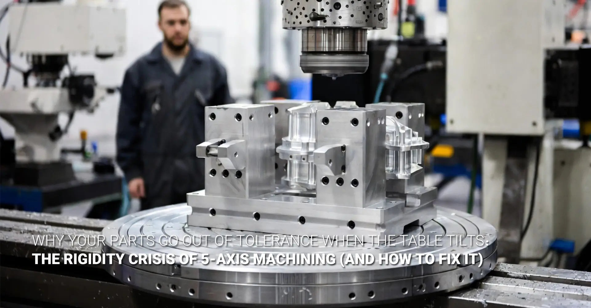
You set up a part. The flat cuts come out perfect. Then you tilt the B-axis to 45°, run the same toolpath — and suddenly the walls are chattering, the radii are inconsistent, and your 5-axis CNC machining tolerances are completely blown.
Sound familiar? You're not alone. This is one of the most common — and most costly — problems in production 5-axis work. And the root cause is almost never the toolpath.
Here's the short answer: When a 5-axis table tilts, the distance between the cutting zone and the rotary table creates a lever arm. That lever arm multiplies cutting forces. The result is fixture deflection, tool chatter, and size errors that only appear on tilted cuts. The fix is clearance fixture design — a low-profile, purpose-built workholding strategy that shortens the lever arm without blocking tool access. Keep reading to learn exactly how it works, what the physics look like, and what to ask your machining partner before you commit to a quote.
This article breaks down the full picture — from the physics of why tilted setups lose rigidity, to the diagnostic signs of a failing setup, to the exact fixture design rules that solve it. Whether you're an engineer, a machinist, or a procurement manager, this guide gives you everything you need to make confident decisions.
Table of Contents
- What Is the Lever Arm Effect in 5-Axis CNC Machining and Why Does It Wreck Tolerances?
- How Do You Know Your 5-Axis Setup Is Suffering from Rigidity Loss?
- What Is a Clearance Fixture and How Does It Solve the 5-Axis Rigidity Problem?
- What Materials and Design Rules Produce the Stiffest 5-Axis Fixtures?
- Conclusion
What Is the Lever Arm Effect in 5-Axis CNC Machining and Why Does It Wreck Tolerances?
Most machinists understand that rigidity matters. But far fewer understand how fast rigidity degrades as the workpiece moves away from the rotary table. The lever arm effect machining principle is the core reason why a part that cuts beautifully at B=0° can completely fall apart at B=90°.
When the table tilts, cutting forces no longer push directly into the rigid machine frame and table bearings. Instead, those forces act on a moment arm — the distance from the cutting zone down to the pivot point of the rotary axis. The longer that arm, the more torque the cutting force creates. That torque bends the fixture, deflects the workpiece, and shifts the tool tip away from its programmed position. The outcome is B/C axis deflection that no CAM system automatically compensates for.
Key takeaway: The lever arm effect doesn't just reduce rigidity. It redirects cutting forces into the weakest part of the setup — the fixture height.
The Cubic Relationship: Double the Distance, Deflection Increases 8×
This is the number that surprises most people. Deflection in a cantilevered system is not linear — it scales with the cube of the unsupported length (L³).
| Fixture Height | Relative Deflection | Practical Impact |
|---|---|---|
| 50 mm | 1× (baseline) | Typically within tolerance |
| 100 mm | 8× | Tolerance failure likely |
| 150 mm | 27× | Chatter and size error guaranteed |
A 50 mm tall fixture that deflects 0.01 mm becomes a 100 mm fixture deflecting 0.08 mm. For a part with a ±0.05 mm tolerance, that's already a scrap part — before accounting for tool runout or thermal growth. Understanding machine tool dynamics at this level is what separates a shop that gets it right from one that keeps scrapping expensive parts.
B-Axis vs. C-Axis: Which Tilt Direction Hurts More?
Both axes create lever arm problems, but they act differently. B-axis tilts forward and back — it tends to create bending loads that act along the fixture's most vulnerable axis (height). C-axis rotation introduces twisting loads, which can be more damaging on fixtures with unsupported arms.
The worst case is a combined B/C tilt in a 5-axis simultaneous cut. Here, the cutting force vector changes continuously, and the fixture sees bending and torsion at the same time. No standard vise on a riser block is designed for this. That's why cutting rigidity 5 axis setups demand custom workholding — not off-the-shelf solutions scaled up from 3-axis work.
For industries with especially tight demands — such as industrial machinery components and automotive structural parts — this distinction between B and C axis behavior is critical to predicting where a setup will fail before metal is ever cut.
How Do You Know Your 5-Axis Setup Is Suffering from Rigidity Loss?
Rigidity loss in 5-axis work hides in plain sight. The symptoms look like toolpath errors, worn cutters, or programming mistakes — but the actual cause is fixture deflection. Knowing what to look for saves hours of troubleshooting and prevents repeated scrap cycles.
The fastest way to confirm a rigidity problem is this: if the defect only appears on angled or tilted cuts, and disappears when the same feature is re-cut at B=0°, the fixture is flexing. The toolpath is fine. The fixturing is not.
Diagnostic rule: Chatter that appears at one orientation and disappears at another is almost always a fixturing problem, not a spindle or toolpath problem.
Three Clear Signs of 5-Axis Rigidity Failure
The following symptoms are the most reliable indicators that workholding stiffness has been compromised:
- Chatter marks on tapered walls only — Flat faces cut cleanly, but angled walls show regular, rhythmic tool marks. This is the clearest sign of orientation-dependent stiffness loss.
- Inconsistent radii between front and back faces — A radius that measures correctly on the near face reads out of tolerance on the far face. The fixture is rocking under cutting load.
- Poor surface finish on angled surfaces only — Surface finish failures that correlate with tilt angle, not with feed rate or spindle speed, point directly to mechanical compliance in the setup.

Why CAM Systems Miss This — And Why Machinists Learn It the Hard Way
Here's the uncomfortable truth: most CAM systems simulate the toolpath, not the setup. They verify gouge-free motion and show smooth toolpaths. But they don't model fixture deflection, and they don't account for how vibration dampening fixture performance changes with orientation.
The result is a perfectly verified program that produces out-of-tolerance parts the moment the table tilts past 30°. The machinist adjusts feeds, changes tools, re-probes the part — and nothing works. The real fix — shortening the fixture — never gets tried because the CAM screen showed a clean simulation.
This gap is especially dangerous in high aspect ratio part fixturing, where long, narrow parts need significant table tilt to access deep features. Without FEA-based stiffness analysis or at minimum a rigidity-aware fixture design review, these setups are guesswork.
What Is a Clearance Fixture and How Does It Solve the 5-Axis Rigidity Problem?
A clearance fixture is a purpose-built workholding solution designed to provide full tool access to complex geometry while keeping the workpiece as close to the rotary table as physically possible. It is the primary engineering answer to the lever arm problem.
Unlike a standard vise on a tall riser, a clearance fixture is not generic. It is designed around the specific part geometry, the machine's tilt range, and the primary cutting force directions. Every millimeter of unnecessary height is eliminated. Every structural wall is placed where it adds stiffness — not where it's easiest to machine.
Simple definition: A clearance fixture gives the tool what it needs to reach the part — and nothing else. Less height means less lever arm. Less lever arm means tighter tolerances.
Four Defining Features of a Clearance Fixture
The best clearance fixtures share these characteristics:
- Tapered or angled walls — Instead of vertical walls that force the table to tilt more, the fixture walls are angled to clear the tool shank at shallower table tilts.
- Cutouts and pockets — Material is removed wherever it adds no structural value. This reduces height and weight without reducing stiffness, since mass alone does not add rigidity.
- Ribs oriented along the primary cutting force — Structural ribs are placed in the direction of maximum cutting load, not simply as a grid pattern.
- Low overall profile — The part sits as close to the table surface as tool access allows. Even a 20 mm height reduction can cut deflection by more than 50% due to the cubic relationship.
The Torque Tube Analogy — and Why Topology Matters
A common misconception is that heavier fixtures are stiffer. In reality, a well-designed torque tube fixture — a thin-walled tube-like structure — can be dramatically stiffer than a solid block of the same height, because it resists torsion efficiently without unnecessary mass.
Topology-optimized fixtures take this further. By using FEA to identify exactly where stress flows under cutting loads, engineers can remove material from low-stress zones and concentrate it at high-stress paths. The result looks unconventional — organic shapes, cutouts in unexpected places — but the stiffness-to-height ratio is far superior to conventional designs.
Another powerful approach is the angled riser block: instead of tilting the machine table to reach an angled feature, the fixture itself is angled to present that feature to the spindle at B=0°. This keeps the lever arm short and the cutting forces directed straight into the table — the stiffest possible load path. Our CNC machining service team uses this approach regularly on complex parts that other shops approach with oversized risers and long-reach tooling.
What Materials and Design Rules Produce the Stiffest 5-Axis Fixtures?
Fixture geometry matters. But material choice matters nearly as much — especially when fixture height cannot be reduced as far as desired. Choosing the wrong material for a tall fixture can erase all the benefits of a well-designed geometry.
The governing metric is specific stiffness — the elastic modulus of the material divided by its density. For a fixture that cannot be shortened, you want the highest modulus possible in the structural members.
Rule of thumb: Steel is not three times heavier than aluminum — it is three times stiffer for the same cross-section. For a fixed-to-table fixture, that weight penalty is acceptable.
Material Comparison for 5-Axis Fixture Bodies
| Material | Elastic Modulus | Relative Stiffness | Best Use Case |
|---|---|---|---|
| 4140/4340 Steel | ~200 GPa | 3× aluminum | Main fixture body, tall structures |
| Cast Iron | ~170 GPa | 2.5× aluminum | Base plates, heavy-duty fixtures |
| 6061 Aluminum | ~69 GPa | Baseline | Low-profile fixtures, light clamps |
| Epoxy Granite | ~45–50 GPa | 0.7× aluminum | Vibration damping, specialty setups |
For most production 5-axis work in CNC metals and plastics machining, 4140 pre-hardened steel is the correct choice for any fixture taller than 75 mm. The weight is not a liability — the fixture is bolted to the table and never moves. Aluminum is appropriate for low-profile fixtures or non-structural clamp arms where reduced extended tool length is already managing the lever arm.
The "2× Thickness" Rule and Fixturing Boss Design
Two practical rules apply to virtually every clearance fixture design:
The 2× Thickness Rule: Any cantilevered arm on a fixture — a jaw, a clamp extension, or a support wing — should have a wall thickness at its root equal to at least twice the wall thickness of the arm itself. This prevents the root from being the failure point under cutting load. For custom CNC milling services, this rule is often encoded directly into design review checklists.
Fixturing Boss Design: When designing a part for 5-axis machining, add flat, accessible surfaces near the part edges — "jack pads" or fixturing bosses. These allow the machinist to place additional supports close to the cutting zone, shortening the effective lever arm without redesigning the fixture. This is the simplest DFM (design for manufacturability) action a part designer can take to improve 5-axis rigidity.
For tool chatter reduction on parts that cannot use additional supports, a final option is to machine at reduced radial depth of cut and increase axial engagement. This shifts the cutting force direction and often raises the chatter-free threshold — but it is a workaround, not a root-cause fix.
Also worth noting: CNC turning operations on complex rotational parts face analogous lever arm challenges when parts are chucked with significant overhang. The same physics apply — and the same fixturing principles hold.
Conclusion
Here's what every engineer, machinist, and procurement manager needs to remember about 5-axis CNC machining tolerances:
Tolerance failures on tilted cuts are almost always a fixturing problem — not a programming problem.
The moment a 5-axis table tilts and the workpiece sits on a tall fixture, a lever arm is created. That lever arm multiplies cutting forces by the cube of its length. The result is deflection, chatter, and dimensional drift that no toolpath adjustment will fix.
The solution is clearance fixture design:
- Keep the part as close to the rotary table as possible — every millimeter counts
- Use steel (4140 or 4340) for any fixture body taller than 75 mm
- Orient structural ribs along the primary cutting force — not as a generic grid
- Use angled riser blocks to tilt the part instead of the table whenever possible
- Apply the 2× thickness rule to all cantilevered arms and clamp extensions
- Add fixturing bosses to part designs — flat surfaces near the edges for close-contact support
Before you quote your next complex 5-axis part, ask your machining partner two questions: "Do you design custom clearance fixtures for deep-reach setups?" and "Can you show me a case where fixture redesign solved a tolerance problem?" Their answer will tell you everything you need to know.
A shop that treats workholding as an afterthought will give you chatter marks and scrap rates. A shop that invests in fixture engineering — with steel clearance fixtures, topology-aware designs, and rigidity simulation — will give you consistent, repeatable parts at tolerance. The fixture design isn't an extra cost. It's what you're actually paying for when you choose a precision 5-axis partner.
External Links & Further Reading
[5 axis cnc machining tolerances][^1]
[^1]: A precision engineering resource from AP Precision Metals, Inc., specifying that while standard 3-axis CNC milling holds tolerances from ±0.005″ to ±0.001″ (±0.127 mm to ±0.025 mm), 5-axis CNC machining can achieve tighter tolerances as close as ±0.0005″ (±0.013 mm) due to enhanced dimensional stability and significantly reduced setups across all axes.[reference:0]
[^2]: A technical product review from Modern Machine Shop (MMS Online) detailing the YCM RX65+ five-axis VMC, which is engineered specifically for speed, rigidity, and accuracy. Its construction from rugged Meehanite castings, hand-scraped joints, and roller guideways across all axes provides high cutting rigidity with vibration dampening, enabling consistent precision when machining tough materials and maintaining tight tolerances on complex parts.[reference:1]


