Why Does One 0.2mm Radius Turn a 3-Day CNC Program Into a 3-Hour Job?
Why Does One 0.2mm Radius Turn a 3-Day CNC Program Into a 3-Hour Job?
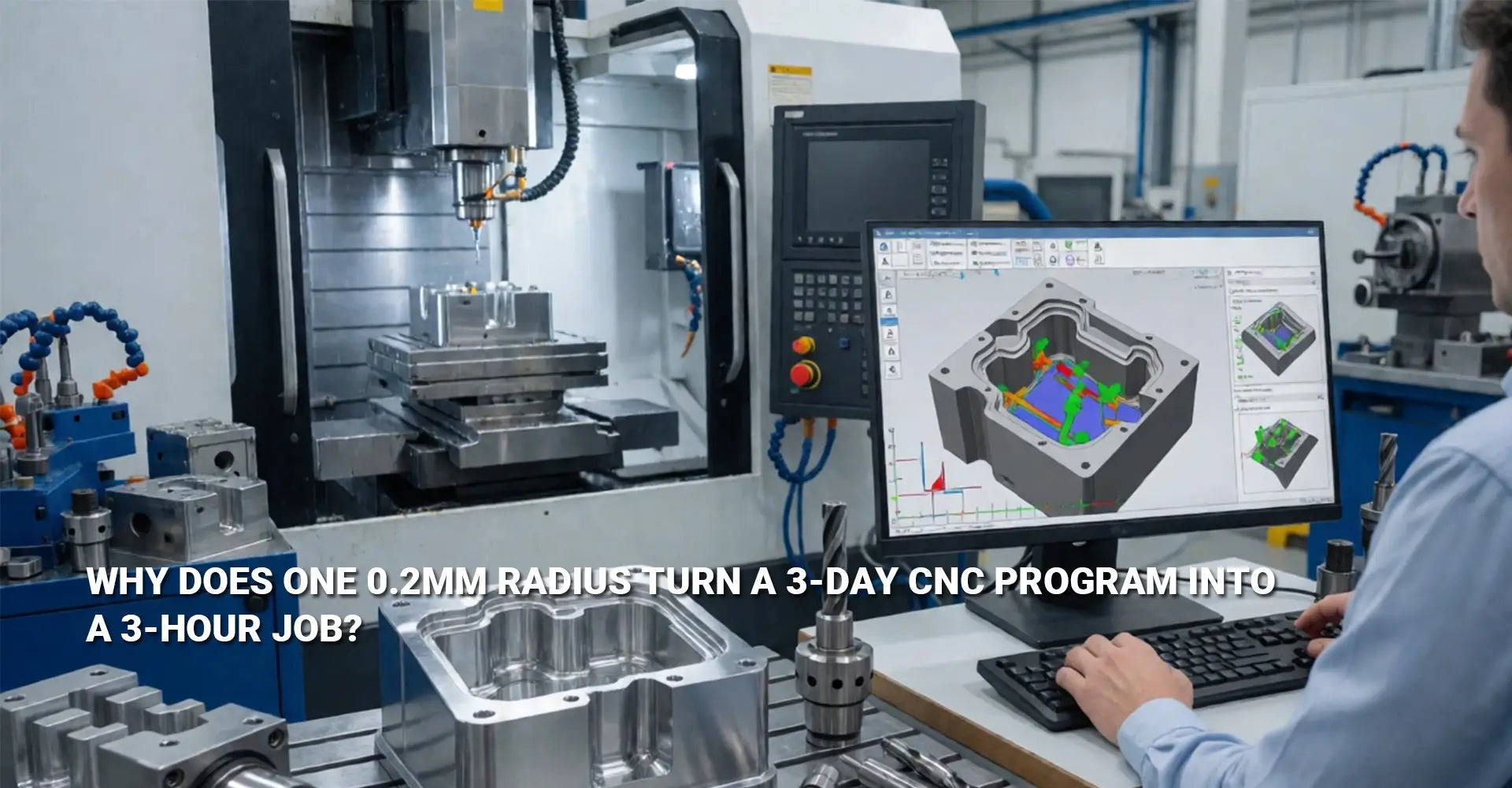
A tiny curve on a drawing can wreck a machinist's whole week. Somewhere on a steel part, an engineer draws a smooth 0.2mm radius where two surfaces meet. It looks harmless on screen. But once that drawing reaches the shop floor, it can turn a simple 5 axis cnc milling steel job into a three-day fight with tool collisions. This guide walks through why that happens, what it costs, and how to stop it before the CAM programmer ever opens the file.

Quick Answer: A radius that is too small forces the CAM programmer to pick a very small end mill. That small tool needs a small holder to reach the corner. But the machine's spindle, collet nut, and shank are still large. When the 5-axis table tilts to follow the surface, that oversized holder can crash into the part. Fixing the radius on the drawing — not on the shop floor — is almost always faster and cheaper.
Design choices on paper turn into real machine moves once a part hits the mill. So before diving into fixes, it helps to see exactly why steel parts with tight curves cause so much trouble on a 5-axis machining service. The next few sections break down the physics, the cost, and the checklist that keeps this from happening to your next quote.
Table of Contents
- Why Does a Small Internal Radius Force a Tiny Cutting Tool?
- Why Do Tool Holders Collide More Than Cutting Tools in 5-Axis Machining?
- What Does an Interference Nightmare Actually Cost in Programming Time?
- How Can Engineers and Procurement Managers Prevent This Before Quoting?
Why Does a Small Internal Radius Force a Tiny Cutting Tool?
Geometry does not bend for convenience. An end mill is round, so it can only cut a corner that matches or exceeds its own radius. This one fact drives almost every collision problem in internal corner radius design, and it is the first thing to check on any steel part headed for a 5-axis mill.
In short: if a drawing calls for a 0.2mm internal radius, the cutting tool must be 0.4mm in diameter or smaller. A tool that small cannot reach deep into a pocket without bending or breaking. The safer rule is simple: keep internal radii at least 1mm, or at least one-third of the pocket depth, whichever is larger.
A 5mm deep pocket needs at least a 1.7mm radius to stay clear of trouble. A 15mm deep pocket needs roughly 5mm. These numbers matter because a bigger radius allows a bigger, sturdier tool, which in turn allows a bigger tool holder. That extra room is what keeps 5 axis workholding clearance intact once the machine starts tilting around a curved surface. It also affects concave surface machining, since curved pockets often combine tight radii with steep walls, doubling the interference risk. Materials matter here too. Steel behaves differently than aluminum or plastic under a small-diameter tool, so it helps to confirm tool and radius limits against the material properties for metals and plastics before the drawing is locked. Suppliers who run a custom CNC milling service can usually flag these radius issues during the first review, well before a single tool touches the steel.
Why Do Tool Holders Collide More Than Cutting Tools in 5-Axis Machining?
Most engineers picture a crash as the cutting edge gouging the part. That does happen, and checking for it is called gouge check machining. But on a 5-axis mill, the bigger risk usually is not the tip of the tool. It is everything above it.
Simply put: a tool holder collision means the shank, collet nut, or spindle housing hits the part, the fixture, or the machine table. This is different from a gouge, and it is a much more common cause of tool interference 5 axis machining problems on steel parts with tight internal features.
Here is why it happens. To follow a curved or angled surface, a 5-axis machine tilts the tool around one or two rotary axes. As the tool tips over, the holder swings closer to the part. A cutting edge that clears the surface by a wide margin can still send its holder crashing into a nearby wall. Modern CAM software runs CAM collision detection to catch these events before the program ever reaches the machine, flagging any spot where the holder path overlaps solid material. The software is good at finding the problem. It is not always good at solving it without help, which is where manual programming time starts to add up, as the next section shows.
What Does an Interference Nightmare Actually Cost in Programming Time?
Every flagged collision needs a fix, and someone has to make that fix by hand. This single fact explains most of the swings in 5 axis programming cycle time on steel parts with poor internal geometry.
Here's the short version: when CAM software finds a holder collision, the programmer has to find every affected toolpath segment, rotate the tool axis to create clearance, then rerun the simulation to check for new problems elsewhere. On a complex surface, this can repeat hundreds of times.
The manual fix for each bad segment is called tool path avoidance programming, and it is slow, repetitive work. A programmer might spend an entire night rotating the tool a few degrees at a time, just to clear one pocket wall. Multiply that across a full part, and a job that should take three hours can stretch into three full days of overtime. This kind of delay hits harder on parts with tight deadlines, such as steel brackets bound for automotive assembly lines or structural components for industrial machinery, where a missed delivery window can stall an entire production run. The good news is that almost none of this cost is required. It only shows up when the drawing leaves the interference problem for someone else to solve later.
How Can Engineers and Procurement Managers Prevent This Before Quoting?
The fix is cheapest before a single line of CAM code is written. That is the entire idea behind DFM for 5 axis parts: catching interference risks on the drawing, not on the machine.
Bottom line: ask for a design-for-manufacturing review before quoting starts. A short checklist can catch most radius and clearance problems in minutes.
A workable audit looks like this:
- Check every internal corner. Is the radius at least 1mm, and at least one-third of the pocket depth?
- Check every concave transition. Can a standard 20-32mm tool holder pass through without touching a wall?
- Ask for a DFM review. A supplier who flags radius problems for free is protecting your schedule, not padding an invoice.
- Ask about tool access. A quick question like "can a 20mm holder reach this pocket?" often reveals a problem in seconds.
It also helps to work with a shop that handles more than one process. A supplier offering CNC turning alongside milling can often suggest a design tweak, such as splitting a feature across two operations, that avoids the tight-radius trap altogether. These conversations, held early, are what separate a smooth quote from a three-week delay.
Conclusion
Geometry is not just an engineering detail. It is a procurement risk that shows up on the invoice. A 0.2mm radius that looks fine in CAD can add days to a programming schedule, push back delivery, and quietly raise the price of a part. The fix costs nothing but attention: keep internal radii at or above the one-third-of-depth rule, check that a real tool holder can reach every pocket, and ask for a DFM review before the first toolpath is drawn. The gap between a 3-hour program and a 3-day one is usually just one number on a drawing. Change it in CAD, not at 2 AM on the shop floor.
Recommended External Resources
[5 axis cnc milling steel][^1]
[tool interference 5 axis machining][^2]
[tool holder collision avoidance][^3]
[internal corner radius design][^4]
[5 axis programming cycle time][^5]
[concave surface machining][^6]
[^1]: A 2025 Elsevier study presenting a Sequential Quadratic Programming (SQP)-based framework for five-axis flat-end milling toolpath optimization. It simultaneously optimizes feed direction and tool orientation (inclination and tilt angles) to maximize machining width and improve path smoothness for higher material removal rates (MRR) in steel machining[reference:0][reference:1].
[^2]: A 2024 Elsevier study presenting a custom post-processor using a Particle Swarm Optimization (PSO) algorithm for 5-axis machine tools. It integrates collision and interference avoidance between the tool and workpiece into a multi-objective optimization that compensates for non-linear geometric errors[reference:2].