Why Does Anodizing Show Dark Streaks After 5 Axis Milling Services?
Why Does Anodizing Show Dark Streaks After 5 Axis Milling Services?
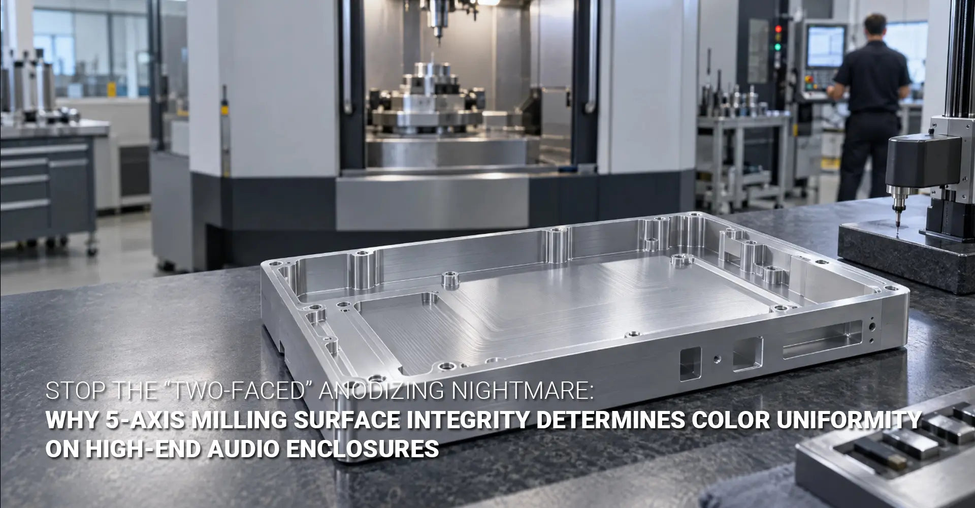
If your anodized aluminum parts came back with dark streaks or patchy shadows, the anodizer is probably not the problem. In most cases, the real cause hides inside the milling step that happened before the parts ever touched a chemical tank. A part can look perfect under normal light and still fail once it is anodized. That is because anodizing does not hide surface flaws. Instead, it reveals every one of them.

Quick answer: Dark streaks and shadows after anodizing almost always trace back to three machining issues: leftover tool marks, heat from high-speed cutting, and coolant residue trapped in the surface. Fix these three things during 5 axis milling services, and most cosmetic anodizing defects disappear before they start.
So, why does this happen so often, and why does it matter so much for premium products like audio enclosures? Because anodizing is a chemical process, not a paint job. It grows a layer of oxide directly out of the aluminum surface. Any tiny flaw in that surface becomes part of the final color. This guide walks through the science, the causes, and the exact steps a procurement manager can take to stop the problem before it reaches a customer's desk.
Table of Contents
- The "Two-Faced" Anodizing Problem
- How 5-Axis Milling Creates Hidden Defects
- The Science of Anodizing and Surface Uniformity
- The 5-Axis Advantage for Perfect Anodizing
- The Pre-Anodizing Cleaning SOP
- The Procurement Manager's Checklist
- Conclusion
Why Does a Mirror-Like Milled Surface Turn Dark After Anodizing?
A part comes off the mill looking flawless. It is smooth, shiny, and ready for finishing. Then it comes back from anodizing with dark streaks running across one face, while the rest looks bright and even. This is sometimes called the "two-faced" anodizing problem, and it shows up constantly in online machining forums.
Here is the quick version: anodizing does not add color the way paint does. It converts the outer layer of aluminum into an oxide coating, and that coating takes on color based on how the metal underneath was prepared. So when a customer complains about anodizing streaks and shadows, the honest answer is usually that the milling process, not the anodizing tank, created the flaw.
This matters even more for parts with strict cosmetic standards. High-end audio enclosures are judged on how they look as much as how they perform. A single batch of parts with visible shadows can mean rejected shipments, angry customers, and a scramble to figure out what went wrong. Understanding the real cause early can save weeks of back-and-forth between machining and finishing teams.
How Do Tool Marks and Chatter Cause Anodizing Shadows?
Every cutting tool leaves a pattern behind, even when that pattern is too small to see with the naked eye. Under normal light, a milled aluminum surface can look completely smooth. But anodizing acts like a magnifying glass for these micro-grooves, because the oxide layer forms differently along ridges compared to flat areas.
In short, tool marks after anodizing show up as fine lines or shadow bands that were invisible before the chemical bath. Chatter marks anodizing defects are a related issue. Chatter happens when the tool vibrates slightly during cutting, leaving an uneven, wavy texture instead of a clean pass. Both problems come from the same root: inconsistent contact between the cutting edge and the metal.

The fix starts with toolpath design. A constant chip load keeps the cutting force steady across the whole surface, which reduces the risk of chatter. Sharp, polished tools with the correct rake angle also cut more cleanly, leaving fewer marks for the anodizing bath to expose. When a shop machines cosmetic aluminum parts, this level of attention to 5-axis machining surface integrity is not optional. It is the difference between a part that passes inspection and one that gets sent back.
Does High-Speed Machining Heat Change How Aluminum Anodizes?
Cutting metal quickly generates friction, and friction generates heat. During high-speed milling, that heat can build up right at the surface of the part, even if the tool and coolant seem to be working fine. This localized heating can alter the aluminum's surface chemistry in ways that are hard to spot until the part reaches the anodizing tank.
High-speed machining heat is a common but often overlooked cause of cosmetic anodizing defects. When the surface microstructure changes from heat, the oxide layer that forms during anodizing does not grow at the same rate everywhere. As a result, some areas anodize lighter, some darker, and the difference becomes obvious once the part is finished.
Reducing this risk means paying close attention to spindle speed, feed rate, and coolant delivery, especially on thin-wall or complex geometry parts like 5-axis milling aluminum audio components. Slowing down slightly in tricky sections, or adjusting the toolpath to avoid dwelling in one spot too long, can prevent the kind of heat buildup that leads to uneven anodizing later.
Why Does Coolant Residue Ruin Anodizing Color Consistency?
Coolant does an important job during machining. It carries away heat, flushes out chips, and helps the tool cut cleanly. However, coolant can also leave behind a thin film of oil, additives, or trace metals on the part surface. This film is often invisible to the eye, but it can block the even chemical reaction that anodizing depends on.
Coolant residue anodizing defects usually appear as blotchy or hazy patches, sometimes concentrated near tight corners where cleaning fluid tends to pool. Because anodizing relies on direct contact between the aluminum surface and the chemical bath, any barrier — even a microscopic one — disrupts chemical conversion coating uniformity across the part.

This is why cleaning before anodizing deserves as much attention as the milling step itself. A part can be machined perfectly and still fail if it goes into the anodizing tank with leftover residue on its surface. Confirming a clean surface for anodizing before parts leave the machine shop protects both the finish quality and the schedule.
What Should a Procurement Checklist Include for Cosmetic Anodized Parts?
For a procurement manager, the goal is simple: get parts that anodize evenly, every time, without expensive rework. That starts with asking the right questions before production begins, not after a batch comes back with visible flaws.
A strong purchase order should specify a controlled toolpath strategy for cosmetic surfaces, high-pressure coolant delivery for finishing passes, and a documented cleaning procedure before anodizing. It should also require anodized first-article samples for color approval, so problems get caught on a small batch instead of a full production run.
Ask your supplier directly: What toolpath do they use to control chatter and heat? Do they run high-pressure through-spindle coolant? Can they share pre-anodizing surface roughness data? A supplier who answers these questions with specifics is serious about cosmetic quality. One who cannot is a risk worth avoiding.
Getting this right pays off in a very real way. One manufacturer moved from a 15 percent batch rejection rate, with every part hand-polished, down to under 1 percent rejection and no polishing at all. That kind of polishing cost reduction adds up fast across large production runs, and it starts with machining the surface correctly the first time, not fixing it afterward with manual labor at a polishing service.
Conclusion
Anodizing streaks and shadows almost always start upstream, inside the milling process, not inside the anodizing tank. Tool marks, chatter, high-speed machining heat, and coolant residue each disturb the oxide layer in a slightly different way, and anodizing exposes every one of them. The good news is that all four causes can be controlled with the right toolpath strategy, the right coolant approach, and a documented cleaning procedure before parts ever reach the finishing line.
For procurement managers sourcing cosmetic parts like audio enclosure CNC machining, the path forward is clear. Specify surface controls on the drawing, ask suppliers pointed questions about their process, and require anodized first articles before committing to full production. Anodizing color consistency is not a matter of luck. It is a direct result of how well the part was milled, cleaned, and prepared before it ever touched the anodizing tank.
External Links Recommendation:
[anodizing streaks and shadows][^1]
[tool marks after anodizing][^2]
[coolant residue anodizing defects][^3]
[5-axis milling aluminum audio components][^4]
[high-speed machining heat][^5]
[chemical conversion coating uniformity][^6]
[^1]: A detailed finishing.com discussion thread covering streaking and shadow defects in anodized extrusions. It explains that streaks often originate from the extrusion quality and microstructure rather than the anodizing process itself. The thread recommends specific corrective actions including buffing at 90 degrees to the streak direction, reducing alkaline etch concentration, and discontinuing glass beading which can work-harden surfaces unevenly. It also discusses shadow lines caused by parts touching on the rack and solutions for better part spacing.
[^2]: An Xometry Pro engineering forum thread that directly addresses whether anodizing can mask machining marks. The answer is clear: anodizing builds up vertically on the surface and will **not** fill in machining marks, so scratches and tool marks remain visible under the right lighting. The thread recommends post-processing options to minimize marks before anodizing, including tumbling, bead blasting for flat surfaces, and electropolishing for complex geometries.