Concentricity vs. Runout: Which GD&T Control Prevents Your Parts from Failing Inspection?
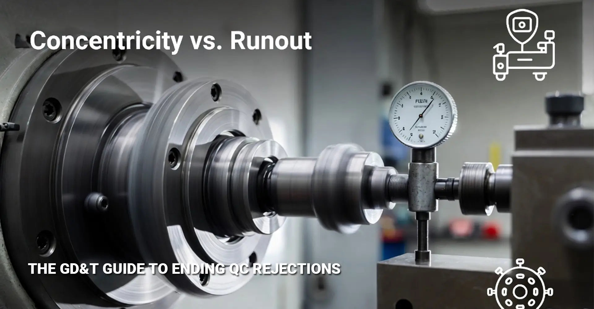
Concentricity vs. Runout: Which GD&T Control Prevents Your Parts from Failing Inspection?

Quality control rejections cost manufacturers thousands of dollars in rework, delays, and strained supplier relationships. Many of these failures stem from a single source of confusion—misunderstanding the difference between concentricity and runout on technical drawings. When your CNC turning parts come back with "out of spec" tags, the root cause often isn't poor machining but rather unclear specifications that confuse inspectors and machinists alike.
Quick Answer: What You Need to Know Right Now
Key Takeaways:
- Runout measures surface wobble directly with a dial indicator (simple, fast, functional)
- Concentricity measures theoretical centerline alignment (complex, expensive, rarely necessary)
- One-setup machining naturally achieves both controls when turning coaxial features
- Best practice: Specify runout instead of concentricity for 95% of applications
- Measurement difference: Runout = TIR reading; Concentricity = calculated median points
- Cost impact: Runout verification takes minutes; concentricity can take hours
- Functional value: Runout controls actual wobble; concentricity controls mathematical abstraction
Understanding these two GD&T controls isn't just academic—it directly impacts whether your parts pass inspection, how much you pay for measurement, and whether your CNC machining service can realistically achieve the specification. Let's break down exactly what each control means and when to use it.
Table of Contents
- What Is Runout and Why Does It Matter for Rotating Parts?
- What Is Concentricity and Why Is It So Difficult to Measure?
- Concentricity vs Runout: What Are the Critical Differences?
- How Does One-Setup Machining Solve Both Tolerancing Challenges?
What Is Runout and Why Does It Matter for Rotating Parts?
Runout is the most practical GD&T control for rotating components. When you spin a shaft, bearing seat, or any cylindrical feature, runout tells you exactly how much that surface wobbles relative to a datum axis. This measurement directly correlates with how smoothly your part will perform in assemblies, making it invaluable for automotive applications where bearing surfaces and rotating shafts must meet strict performance standards.
Here's what makes runout valuable: You can measure it in seconds with a $50 dial indicator. Mount the part between centers or in V-blocks, zero your gauge, rotate the part one full revolution, and read the total indicator reading TIR. That number is your runout value—no calculation, no complex equipment, no ambiguity. The simplicity of this measurement method makes it ideal for shop floor verification during production runs.
Runout controls two things simultaneously: how round the surface is (circularity) and how centered it is on the rotation axis (coaxiality). This composite nature makes it incredibly functional. If a bearing journal has 0.002" runout, you know that bearing will rotate smoothly with minimal vibration. The measurement corresponds directly to real-world performance.
Additionally, there are two types: circular runout (measured at individual cross-sections) and total runout (measured across the entire surface length). For most turning applications, circular runout provides sufficient control while remaining simple to verify during production. Therefore, when you're working with precision components for industrial machinery, GD&T runout control becomes your first line of defense against functional failures.
What Is Concentricity and Why Is It So Difficult to Measure?
Concentricity takes a completely different approach. Instead of measuring the surface directly, it evaluates whether the median points of a cylindrical feature align with a datum axis. Understanding concentricity tolerance meaning requires recognizing that this control focuses on theoretical geometry rather than physical surfaces.
Think of it this way: Concentricity asks "Is the invisible centerline of this cylinder perfectly aligned with the datum axis?" To answer that question, you must measure the surface at multiple cross-sections, calculate the median point of each cross-section (the center between the highest and lowest points), and then determine how far those median points deviate from the datum axis. This requires either a coordinate measuring machine (CMM) or extensive manual calculation.
The complexity doesn't end with measurement. Concentricity has a fundamental weakness: it ignores surface form entirely. A part could have severe lobing or ovality (poor circularity) but still show perfect concentricity if those irregularities are symmetrical around the median points. This means a part can pass concentricity inspection yet fail functionally because the surface wobbles excessively during rotation.
Furthermore, different measurement methods often produce different results for the same part, leading to disputes between suppliers and buyers. When it comes to how to measure concentricity, even experienced quality engineers disagree on the best approach. The ASME Y14.5 standard has essentially deprecated concentricity for new designs, recommending runout or positional tolerances instead because they provide clearer, more verifiable control. Consequently, most custom CNC milling services actively discourage clients from specifying concentricity unless absolutely necessary.
Concentricity vs Runout: What Are the Critical Differences?
Now that we've defined each control individually, let's compare them side-by-side so you can make informed decisions on your drawings and inspection reports. The debate of concentricity vs runout comes down to practical measurability versus theoretical precision.
Comprehensive Comparison
| Aspect | Runout | Concentricity |
|---|---|---|
| What it measures | Surface variation during rotation (wobble) | Alignment of median points to datum axis |
| Measurement method | Dial indicator + rotation = TIR reading | CMM or calculated median points |
| Measurement time | 30 seconds to 2 minutes | 15 minutes to 1 hour |
| Equipment cost | $50-$500 (dial indicator) | $50,000+ (CMM) or extensive hand calculation |
| Controls form? | Yes (includes circularity effects) | No (ignores surface irregularities) |
| Functional correlation | Direct (measures actual wobble) | Indirect (theoretical centerline) |
| Shop floor friendly? | Yes | No |
| Standard recommendation | Preferred for new designs | Deprecated in ASME Y14.5 |
| Repeatability | Excellent (±0.0001") | Poor (varies by method) |
| Training required | Minimal (30 minutes) | Extensive (multiple days) |
Here's the relationship that matters most for practical applications: Perfect runout essentially guarantees acceptable concentricity. If a surface has zero TIR (perfect runout), it's both perfectly round and perfectly centered, which means its median points naturally align with the rotation axis. However, the reverse is not true—perfect concentricity does not guarantee acceptable runout because surface irregularities can still cause wobble.
This asymmetric relationship is why experienced designers default to runout specifications. When you specify runout, you're controlling the functional characteristic (wobble) that matters for bearing fits, sealing surfaces, and dynamic balance. When you specify concentricity, you're controlling a mathematical abstraction that's difficult to measure and doesn't guarantee functional performance.
Therefore, unless you have a specific reason requiring concentricity (extremely rare in practice), runout provides better control with easier verification. In fact, resolving QC inspection failures often begins with simply replacing concentricity callouts with runout tolerances on technical drawings. This single change eliminates measurement ambiguity while maintaining functional control.
How Does One-Setup Machining Solve Both Tolerancing Challenges?
There's a manufacturing secret that makes both concentricity and runout concerns almost disappear: machining all coaxial features in a single setup without removing the part from the chuck. This approach represents the gold standard for achieving one setup machining accuracy.
When a machinist clamps a workpiece in a lathe chuck and machines multiple diameters without unclamping, every diameter shares exactly the same rotation axis. The datum diameter, the bearing journals, the thread sections—all are perfectly coaxial because they were created by the same spindle axis during the same setup. This inherently produces extremely tight runout (often 0.0005" or better) and perfect concentricity without any special effort or measurement.
To leverage this manufacturing advantage, designers should follow a clear specification strategy. First, establish one critical feature as your primary datum (typically labeled -A-). This will be the feature clamped in the chuck. Understanding the datum axis in turning is crucial—it defines the reference from which all other features are measured and manufactured.
Second, add a manufacturing note to your drawing: "Diameters -B-, -C-, and -D- must be machined in the same setup as datum -A-." This instruction tells the machinist exactly how to achieve the required accuracy. Third, apply runout tolerances from the secondary diameters back to datum -A- rather than using concentricity.
This combination—one-setup machining plus runout control—gives you parts that function correctly, can be measured easily on the shop floor, and avoid the measurement disputes that plague concentricity specifications. Even better, it works with the natural capabilities of turning processes rather than fighting against them.
Machinists appreciate this approach because it's clear and achievable. Inspectors appreciate it because verification is straightforward. Buyers appreciate it because parts pass inspection consistently without expensive measurement debates. When you combine intelligent tolerancing with proper manufacturing instructions, your supplier's capabilities align perfectly with your functional requirements.
Conclusion
Making the right choice between concentricity and runout isn't just about following GD&T standards—it's about creating drawings that produce functional parts while avoiding costly inspection failures.
For 95% of applications involving rotating or coaxial cylindrical features, runout is the superior choice. It measures what actually matters (surface wobble during rotation), uses simple and affordable equipment (dial indicators), and correlates directly with functional performance. Concentricity, while mathematically precise, creates measurement challenges that often cost more than any functional benefit it might provide.
The smartest approach combines three elements: specify runout tolerances on your drawings, establish clear datum references, and add manufacturing notes requiring one-setup machining for coaxial features. This trilogy ensures your parts can be made accurately, measured reliably, and will function as intended.
If you're currently dealing with inspection failures on turned parts, review whether the drawing specifies concentricity when runout would work better. That single change often resolves weeks of supplier disputes and rework loops. By understanding the practical differences between these two controls, you can write specifications that support both manufacturing efficiency and product quality—creating a win-win situation for everyone involved in the production chain.
Recommended Resources
[Concentricity vs runout][^1]
[GD&T runout control][^2]
[Concentricity tolerance][^3]
[Total indicator reading TIR][^4]
[Datum axis in turning][^5]
[Surface Wobble Measurement][^6]
---
[^1]: Understanding the difference is crucial for precise engineering and manufacturing, ensuring quality and compliance in designs.
[^2]: Exploring effective methods for GD&T runout control can enhance your quality assurance processes and improve product reliability.
[^3]: Understanding concentricity tolerance is crucial for precision in engineering and manufacturing, ensuring parts fit and function correctly.
[^4]: Exploring TIR will enhance your knowledge of precision measurement techniques, vital for quality control in machining processes.
[^5]: Understanding the datum axis in turning is crucial for precision machining and ensuring quality in manufacturing processes.
[^6]: Exploring surface wobble measurement techniques can enhance your knowledge of quality control in engineering and manufacturing.


Hello. This was a very good explanation of this topic. It seems this has been and will always be a problem with trying to measure. We here at the machine shop i work at also push the same idea of having features machined at the same time when possible. Unless something is really wrong, if diameters are made within the same setup, you can almost grantee that those features will be good, well within .001. When we do have a concentricity callout on a print, we also go straight to a v-block and indicator. its the best way to get a reliable result and fast. I am a Zeiss cmm programmer and actually building all the necessary features to get results is very time consuming. If the results were bad we are back to square 1 because we like to check things on the rock (granite) to confirm or deny results (going back to old school rock checks). Concentricity is just not a characteristic to get reliable numbers that can correlated back to the cmm. So, you end up back at questioning everything again. Runout is just the way to go and thats it. Thanks again for the detailed write up. (the pictures with explanations really helped alot as well) :)