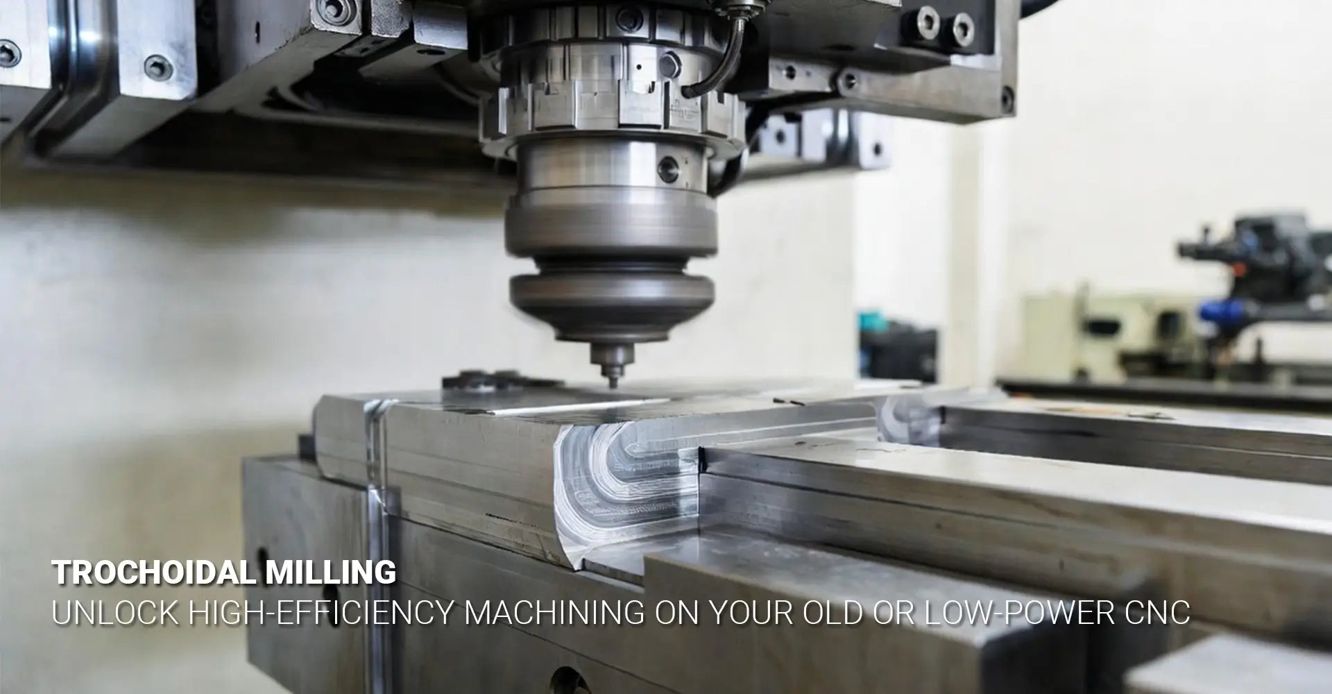
What Is Trochoidal Milling and How Does It Help Old CNC Machines Cut Hard Steel?
What Is Trochoidal Milling and How Does It Help Old CNC Machines Cut Hard Steel?
Machining hard materials on older CNC equipment doesn't have to mean constant tool breakage and scrapped parts. Many shops struggle with limited spindle power, worn components, and rigid setups that can't handle the shock loads of conventional milling. However, there's a proven strategy that lets even underpowered machines tackle tough jobs successfully.
Quick Answer: Trochoidal Milling at a Glance
| Aspect | Details |
|---|---|
| What it is | A curved, looping toolpath that keeps tool engagement constant and small |
| Main benefit | Cuts cutting forces by 40-60% compared to conventional methods |
| Best for | Hard steel, old machines, low-rigidity setups, DIY CNCs |
| Key settings | 5-10% radial stepover, high feed rates, full axial depth |
| Time trade-off | Slightly longer paths, but prevents tool breakage and part scrap |
Traditional straight-line toolpaths create massive force spikes when the cutter enters full-width cuts. This causes chatter, rapid tool wear, and frequent failures on machines without robust rigidity. In contrast, a trochoidal milling path uses continuous curves that maintain gentle, consistent contact throughout the entire operation.
Table of Contents
- What Is Trochoidal Milling and How Does It Differ From Standard Toolpaths?
- How Does Constant Engagement Reduce Cutting Forces and Heat?
- What Parameters Should You Use for Hard Steel on Low-Power Machines?
- Can You Program Trochoidal Paths Without Expensive CAM Software?
What Is Trochoidal Milling and How Does It Differ From Standard Toolpaths?
Most machinists learn to mill slots and pockets using back-and-forth linear passes. The tool plunges in, cuts across the full width, then returns along the same path. While this works fine for soft materials on rigid machines, it creates serious problems when cutting harder steels.
A trochoidal path creates continuous circular loops along the cutting direction, maintaining a tiny radial stepover (5-10% of tool diameter) instead of full-width engagement. This keeps chip load constant throughout the entire cut. Think of it like drawing a spring that moves forward—each loop slightly overlaps the previous one, progressively removing material without ever slamming into a solid wall.
The geometry behind this approach fundamentally changes how your tool interacts with the workpiece. Instead of the entire flute length engaging at once (creating a massive radial force), only a small arc of the cutter touches material at any moment. This is the essence of a constant tool engagement strategy, which distributes wear evenly and prevents the sudden deflection that causes chatter.
Additionally, because the tool never stops moving, it avoids the rubbing and heat buildup that occurs when conventional paths require direction changes. The continuous motion means chips evacuate cleanly, and the cutter never dwells in one spot long enough to work-harden the surface. For operations involving CNC machining service providers working with challenging materials, this approach dramatically improves reliability.
How Does Constant Engagement Reduce Cutting Forces and Heat?
The physics of metal cutting reveal why trochoidal toolpaths perform so well on difficult materials. When a cutter engages full-width in a conventional slot, it must shear through a large cross-section of material simultaneously. This generates enormous forces that deflect the tool, stress the spindle bearings, and overload weak drive systems.
By limiting radial contact to 5-10% of the cutter diameter, trochoidal milling keeps cutting forces low and consistent. Each small chip carries heat away before it builds up, preventing work hardening and tool wear. Instead of one massive chip per tooth, you get many smaller chips that evacuate easily and don't retain as much thermal energy.
This approach specifically targets the two biggest enemies of machining hard materials with low power: excessive force and concentrated heat. When force peaks drop by 40-60%, several benefits emerge immediately:
- Less spindle deflection, meaning better surface finish and dimensional accuracy
- Reduced vibration, which prevents chatter even on machines with worn ways or loose gibs
- Lower power draw, allowing smaller spindles to maintain speed under load
- Extended tool life, because carbide stays cooler and experiences less shock
Heat management becomes particularly critical when working with tool steels, hardened alloys, or stainless grades. Conventional milling can generate temperatures exceeding 800°F at the cutting edge, which rapidly degrades coatings and causes premature failure. Moreover, the heat doesn't just affect the tool—it also migrates into the workpiece, potentially causing dimensional changes or surface hardening that makes subsequent passes even more difficult.
Trochoidal milling for hard steel solves this by keeping the thermal load distributed across many small cutting events rather than concentrated in one massive engagement. The tool constantly moves into fresh, cool material, and the chips carry away heat before it can accumulate. This thermal advantage becomes especially valuable in automotive applications where precision and surface integrity matter greatly.
What Parameters Should You Use for Hard Steel on Low-Power Machines?
Getting the numbers right makes the difference between success and failure. Many machinists fail with trochoidal milling because they don't adjust their parameters enough from conventional practices. The strategy requires a complete mindset shift regarding how you balance radial engagement, feed rate, and depth of cut.
The Three Critical Settings:
- Radial stepover: 5-10% of tool diameter (smaller for harder materials)
- Feed rate: 2-3x higher than conventional (maintains chip load)
- Axial depth: Up to full flute length (compensates for small stepover)
Let's break down a practical example. Suppose you're cutting a slot in 4140 steel (around 30 HRC) using a 1/2" (12.7mm) carbide endmill on an older machine. Here's how you would set up a high-efficiency milling for old machines operation:
Radial Stepover: Start with 6% of diameter = 0.030" (0.76mm). This tiny engagement is what makes everything else possible. Yes, it seems counterintuitive to take such a small bite, but remember—you'll compensate with depth.
Feed Rate: If your conventional slotting feed was 10 IPM, increase to 25-30 IPM. Because the engagement is so small, you need higher travel speed to maintain proper chip load per tooth. The formula remains the same (feed per tooth × teeth × RPM), but the effective engagement arc changes the calculation.
Axial Depth: Take the full 1.5" flute length if your machine can handle it. Since radial forces are minimal, you won't overload the tool even with aggressive depth. This is how you reduce cutting heat and force while still removing material at a reasonable rate.
Spindle Speed: Keep RPM at the tool manufacturer's recommendation for the material. Don't increase speed to compensate for the small stepover—you're already running higher feed rates.
For even harder materials like D2 tool steel or Inconel, reduce stepover to 4-5% and increase feed proportionally. The principle stays the same: maintain chip load through the combination of small engagement and high feed. This approach proves especially valuable for industrial machinery components that require both precision and material toughness.
One common mistake is keeping conventional feed rates while using trochoidal paths. This creates chips that are too thin, causing rubbing instead of cutting. The tool burnishes the surface rather than shearing it, which accelerates wear and creates poor finishes. Always increase your feed rate when you decrease radial engagement.
Can You Program Trochoidal Paths Without Expensive CAM Software?
Budget constraints shouldn't prevent you from using better strategies. While professional CAM packages include dedicated trochoidal cycles with automatic calculation, you can absolutely implement the core principles using more accessible tools.
While advanced CAM packages automate trochoidal paths, you can implement the strategy manually using circular interpolation (G02/G03) commands or by using free CAM tools like FreeCAD with strategic settings. The principle matters more than the software. Understanding why the method works lets you adapt it to whatever programming environment you have available.
For those practicing DIY CNC trochoidal milling, here are several practical approaches:
Manual G-Code Programming
You can create a basic trochoidal path by programming a series of circular arcs that advance along your desired cutting direction. For example, to mill a 2" long slot:
- Calculate your loop diameter (typically 60-80% of tool diameter)
- Calculate forward step per loop (based on your radial stepover)
- Program G02/G03 arcs that alternate direction while incrementing in X or Y
This requires more setup time but gives you complete control. It works well for simple slots and pockets where the geometry is straightforward.
Free and Low-Cost CAM Options
Several accessible software packages now include adaptive or trochoidal toolpaths:
- FreeCAD (Path Workbench): Includes "Adaptive" strategy that generates trochoidal-style paths
- Fusion 360 (Hobbyist License): Full adaptive clearing with excellent trochoidal implementation
- EstlCAM: Budget-friendly option with decent toolpath strategies
- PyCAM: Open-source with customizable algorithms
The key is finding software that allows you to set very small radial engagement percentages and handles continuous curved motion rather than just linear moves.
CAM Programming for Toolpath Optimization
Even in basic CAM software, you can approximate trochoidal benefits by:
- Using a smaller tool than your slot width and making multiple passes
- Setting radial stepover to extremely low percentages (the software may allow this even without a "trochoidal" button)
- Combining helical entry with very small stepover conventional passes
- Manually editing toolpaths to add circular interpolation where the software generates straight lines
The most important aspect is understanding that you're trying to maintain constant, light engagement throughout the cut. Once you grasp this principle, you can adapt nearly any programming environment to support it. Whether you're working with custom CNC milling services or programming your own machine, the fundamental strategy remains consistent.
For shops working with various materials, from metals to composites, having multiple CNC metals plastics cutting strategies in your repertoire makes you far more capable. Trochoidal milling represents just one tool in a complete machining toolkit, but it's one that can unlock capabilities your machine might not otherwise have.
Conclusion
Trochoidal milling transforms challenging cuts on underpowered machines into reliable, repeatable operations. By maintaining constant, minimal engagement through continuous curved motion, you dramatically reduce the force and heat that cause conventional toolpaths to fail on hard materials. The strategy doesn't require a new machine—just a different approach to programming and parameter selection.
Remember the three key parameter changes: reduce radial stepover to 5-10% of tool diameter, increase feed rate by 2-3x to maintain chip load, and utilize full axial depth to compensate for the small stepover. These adjustments work together to create a cutting environment where even older machines can successfully tackle materials that would otherwise be impossible.
Start by testing the strategy on a simple slot in a scrap piece of the material you struggle with most. Program a basic trochoidal path—whether through advanced CAM or manual G-code—and observe how differently your machine behaves. Listen for the absence of chatter, watch for the consistent chip formation, and note how much cooler the tool runs. Once you experience the difference firsthand, you'll find applications for this approach throughout your shop.
The beauty of trochoidal milling lies not in replacing all conventional strategies, but in providing a reliable solution when standard approaches fail. Therefore, it becomes an essential technique for any machinist working with limited equipment, difficult materials, or both.
Recommended Resources
[Trochoidal milling path][^1]
[High-efficiency milling for old machines][^2]
[CNC Milling for Low-Rigidity Machines][^3]
[Trochoidal milling for hard steel][^4]
[Machining hard materials with low power][^5]
---
[^1]: Understanding Trochoidal milling paths can enhance your machining efficiency and precision, especially in complex operations.
[^2]: Exploring high-efficiency milling for older machines can help you maximize their performance and extend their lifespan.
[^3]: Explore this link to discover effective techniques and tips for optimizing CNC milling on low-rigidity machines.
[^4]: Learn about the advantages of Trochoidal milling for hard steel and how it enhances machining efficiency and tool life.
[^5]: Discover how low power machining can enhance efficiency and reduce costs in hard material processing.


