Custom 5 Axis CNC Machining: Can a Shorter Tool Fix Deep Cavity Chatter and Slow Feeds?
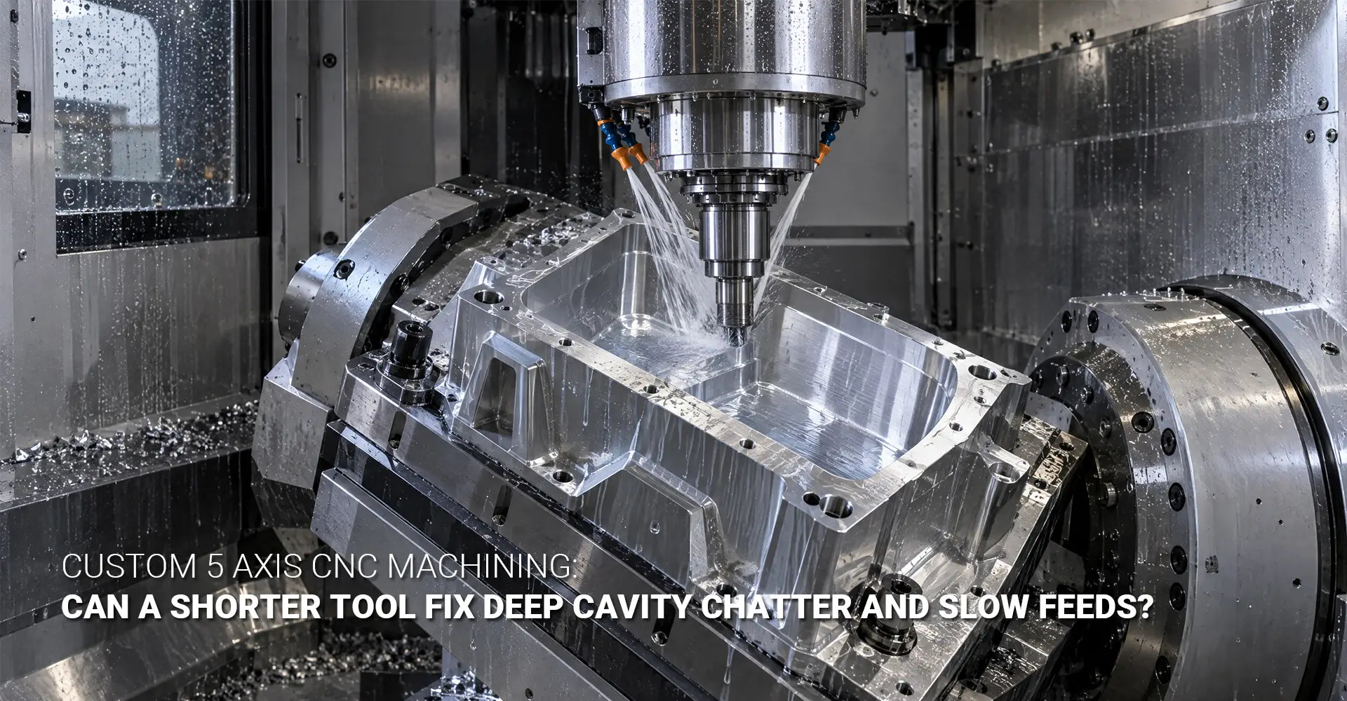
Custom 5 Axis CNC Machining: Can a Shorter Tool Fix Deep Cavity Chatter and Slow Feeds?
Picture a box with a cavity 150 mm deep. Your 3 axis mill needs a very long end mill to reach the floor. Soon the tool starts to shake. The walls look rough, and the machinist slows the feed to stay safe. This problem is common in deep cavity CNC machining, and it costs buyers both time and money. The good news is that custom 5 axis CNC machining can often solve it. By tilting the tool or the part, the machine can use a shorter and stiffer cutter. In this guide, you will learn why chatter starts, how tilting works, what speed gains are realistic, and when 5 axis costs less.

The short answer: Yes, in many cases. A long tool bends and shakes inside a deep cavity. A 5 axis machine can tilt the tool or the part, so a shorter and stiffer cutter can reach the same spot. In other words, 5 axis tilting makes short tool machining possible where a 3 axis mill needs a long tool. As a result, you often get smoother walls, steadier feeds, and fewer rejected parts.
Key Takeaways
| Question | Quick Answer |
|---|---|
| Why does chatter start? | The long tool bends and shakes under cutting force |
| What helps most? | A shorter tool, reached by tilting the tool or the part |
| Is a 200% feed gain real? | Sometimes, but it depends on the job, so test it first |
| When does 5 axis cost less? | When the part is deep, angled, or needs many setups |
| What do I send for a quote? | STEP file, drawing, material, tolerances, and volume |
Now that you have the quick answer, let's look at the details. If you are searching for custom 5 axis CNC machining services for a hard-to-reach part, the four sections below will help you ask better questions. First, we will explain why chatter starts. Next, we will show how tilting works. After that, we will look at the speed gains you can trust. Finally, we will help you judge the total cost.
[Table Of Contents]
- Why Does a 150 mm Deep Cavity Box Cause Chatter on a 3 Axis CNC Mill?
- What Is Custom 5 Axis CNC Machining, and How Does Tool Axis Tilting Work?
- How Much Faster Is a Short Tool, and Is a 200% Feed Gain Real?
- When Is 5 Axis Machining More Cost-Effective Than 3 Axis?
- Conclusion
Why Does a 150 mm Deep Cavity Box Cause Chatter on a 3 Axis CNC Mill?
A deep cavity looks simple on a drawing. In the shop, however, it is hard to cut. First, a 3 axis mill can only move the tool straight up and down, so the cutter must go straight into the box. Next, to reach a floor that sits 150 mm down, the shop needs a very long end mill. As a result, a large part of the tool hangs out of the holder with no support. This long tool overhang is where most of the trouble starts.
Short answer: A long tool is less stiff than a short one. Because of this, cutting force pushes the tool sideways and sets off shaking. This shaking is called cutter chatter. It leaves rough walls, slows the job, and wears out tools faster.
Let's look at the numbers behind this problem. A cutting tool acts like a diving board. The longer the board, the more it bends under the same push. In basic beam theory, bending grows with the cube of the length. So, if you double the tool length, the bending can grow about eight times.
Tool makers also give a helpful rule of thumb. Sandvik Coromant reports that vibration becomes more obvious once the overhang passes about four times the tool diameter. It also advises using the shortest tool length possible. Now picture a 10 mm end mill that must reach 150 mm. Its overhang is about 15 times its diameter. That is far beyond the point where trouble begins.
This bending is called tool deflection. It causes several problems:
- Tapered walls: The tool leans away from the wall, so the top and the bottom do not match in size.
- Size errors: The real cut depth and width change from one pass to the next.
- Chatter marks: Shaking leaves a repeating pattern on the wall.
- Surface waviness: Slow, wave-like changes appear on the surface and may fail a finish check.
- Short tool life: Vibration in CNC milling chips the cutting edge and wears it down faster.
Next, shops react by slowing down. They cut the feed rate, lower the depth of cut, or do both. This keeps the tool alive, but the job takes much longer. In addition, deep cavity milling makes chip removal harder, because chips must travel up a long, narrow channel. Coolant has the same problem, since it cannot easily reach the cutting edge. Chips that stay in the cut get cut again, and the shaking gets worse. Therefore, a slow feed rate is often a sign of a setup problem, not a sign of careful work.
What Is Custom 5 Axis CNC Machining, and How Does Tool Axis Tilting Work?
Now let's look at the fix. A 5 axis machine has the usual X, Y, and Z axes. It also has two rotating axes. Because of these extra axes, the tool or the part can turn while the machine cuts. The programmer then uses tool axis control to pick the exact angle of the cutter at every point on the path. That angle lets the machine reach places that a vertical tool cannot.
Short answer: Tilting means the machine changes the angle between the cutter and the part while it cuts. Instead of pushing a vertical tool straight down into a deep box, the spindle or the table rotates. The cutter then enters from a better angle. Because of this, a shorter tool can often reach the same surface.

There are two common ways to tilt. In the first, the spindle head swings to a new angle. Shops call this spindle tilt machining. In the second, the table turns the part toward the tool. The result is much the same. In both cases, the tool gets closer to the target with less overhang.
Tilting brings three main benefits:
- Shorter tools: Less tool hangs out of the holder, so there is less bending.
- Side access: The cutter can reach deep walls from an angle. It also helps with undercut CNC machining, where a feature sits under an overhang.
- Fewer setups: The machine can reach more faces of the part in one clamp.
However, tilting also adds risk. The holder, the spindle, and the fixture can hit the walls of the part. For this reason, the programmer checks tool holder clearance on every move. Good software also runs 5 axis collision avoidance checks before the first chip is cut. Skilled 5 axis CAM programming is therefore a key part of the process. A poor program can ruin a part, and it can even damage the machine.
Before you pick a shop, ask how the team checks tool reach and fixture access. Look for a partner that offers 5 axis milling services with real collision checks and a clear fixture plan. In short, the machine matters, but the planning matters just as much.
How Much Faster Is a Short Tool, and Is a 200% Feed Gain Real?
Next comes the question every buyer asks: how much faster can the job run? The answer starts with a simple look at 3 axis vs 5 axis machining. A 3 axis mill must use a long tool to reach the floor, so it has to cut gently. A 5 axis mill can use a short tool in a rigid tool setup, so it can cut harder with less shaking. Even so, the real gain depends on the part.
Short answer: A 200% feed-rate gain is possible in some cases, but it is not a promise. The result depends on cavity shape, wall thickness, material, cutter size, tool overhang, holder clearance, fixture strength, spindle power, chip removal, and the CAM plan.
Why does a shorter tool help so much? Think about a ruler held at its very end. It bends easily. Now hold it close to the middle. It feels much stiffer. The same idea applies to a cutter. Here is what a shorter tool can give you:
- Less bending: Less unsupported length means less deflection.
- More stiffness: A stiffer setup allows steadier cutting settings.
- Less chatter: Smoother cuts leave cleaner walls and floors.
- Better size control: Less bending reduces taper and wall variation.
- Longer tool life: Less shaking means less unusual wear.
- Higher feed potential: A steady tool can often run faster than a long, thin one.
A steady cutter can also raise the material removal rate. This simply means that more metal leaves the part each minute. The effect is strong in CNC machining for deep cavity aluminum parts, because aluminum cuts fast when the setup stays stable.
Here is a side-by-side view of the two methods:
| Factor | 3 Axis | 5 Axis With Tilting |
|---|---|---|
| Tool access | Vertical, top-down | Tilts to reach deep or angled features |
| Tool length | Long or extended reach | Often shorter |
| Chatter risk | Higher in deep pockets | Lower with a short, stiff tool |
| Surface finish | May show waves or marks | Can improve when shaking is controlled |
| Cycle time | Often slower | Can be faster if stable feeds are reached |
| Setups | Several for angled faces | Often fewer |
| Best use | Simple, shallow, open pockets | Deep, angled, or complex cavities |
Important: Treat 200% as a best-case result, not a rule. Always run a trial cut with your real material, tool, fixture, and program before you lock in production settings.
A safer claim is this: a shorter tool and a better tool angle often allow much higher stable feeds, shorter cycle times, and a better finish. That is a result you can test, and it is one you can trust once the trial cut proves it.
When Is 5 Axis Machining More Cost-Effective Than 3 Axis?
Many buyers see a higher hourly machine rate and stop right there. That view is too narrow. Real CNC machining cost reduction comes from looking at total cost. This includes setups, scrap, rework, tool cost, and delivery time.
Short answer: 5 axis often costs less when the part is deep, angled, or needs several setups on a 3 axis machine. For simple, shallow parts, 3 axis is usually cheaper. A 5 axis machining DFM review before you buy will show which path fits your part.
Here is where the savings usually come from:
- Fewer setups: Each setup costs time, and each re-clamp adds risk.
- Less scrap: Fewer parts fail because of taper, waves, or rough walls.
- Shorter cycle time: Higher stable feeds lead to real machining cycle time reduction.
- Common cutters: Shorter tools are easier to buy than special extended-reach tools.
- Less rework: Less hand polishing and fixing is needed after the cut.
- One-clamp finishing: Complex features can be finished without moving the part.
- Better repeatability: Batches match each other more closely.
Of course, 5 axis is not always the answer. Shallow, open pockets run well on a 3 axis mill. On the other hand, 5 axis CNC machining for deep cavity parts pays off when depth, angles, or hidden features limit a 3 axis process.
Design tips that lower cost
Good design makes any machining job cheaper. Here are simple rules for deep cavity boxes:
- Avoid extra depth. If the function allows it, cut the depth or split the part in two.
- Give the tool more room. More space around the cutter and holder means gentler tilt angles.
- Add small draft angles. Draft helps tool access and chip flow.
- Avoid sharp inside corners. Larger corner radii allow larger, stiffer cutters.
- Mark the key surfaces. Show which walls need tight tolerance or a fine finish.
- Avoid fully closed pockets. The tool needs a path in.
- Plan for chips and coolant. Deep pockets need a clear way for chips to leave.
What to send for a quote
A complete request saves days of back-and-forth. Please include:
- A 3D model in STEP or IGES format
- A 2D drawing with tolerances and key sizes
- The material grade and stock condition
- Cavity depth, width, wall thickness, and corner radii
- Finish and cosmetic needs
- Prototype count, yearly volume, and delivery date
- Assembly or mating needs
- Heat treatment, surface treatment, and inspection needs
- Photos of past quality problems, if you have them
With these items in hand, a shop can return an accurate 5 axis CNC machining quote much faster.
When you choose a CNC machining supplier for complex parts, ask about tilt limits, collision checks, and trial cuts. Also ask how the shop records inspection results. Hotean offers OEM CNC machining services for both prototypes and production runs. If your part also has round features, a CNC turning step can finish them before milling. These steps matter for housings, gearboxes, and other parts used in industrial machinery.
Need to machine a 150 mm deep cavity box without chatter, taper, or long cycle times? Send us your STEP file, material, tolerances, and production volume for a custom 5 axis CNC machining DFM review.
Conclusion
Deep cavity boxes are hard on long tools. A long reach causes bending, shaking, rough walls, and slow feeds. Tilting the tool or the part lets the machine use a shorter and stiffer cutter instead. As a result, many jobs see steadier cutting, a better finish, and a shorter cycle time.
Here is a quick recap:
- The cause: Long tools bend and shake in deep cavities.
- The fix: Tilting allows shorter, stiffer tools.
- The speed gain: A 200% feed gain can happen, but only in some cases, so always test first.
- The cost view: 5 axis often wins on deep, angled, or multi-setup parts once you count total cost.
- The next step: Share your model, drawing, material, and volume for a design review.
In short, custom 5 axis CNC machining gives you a practical way to cut deep cavities with less risk. Start with a clear model, honest tolerances, and a trial cut. Then you can move to production with confidence.
Recommended External Reading
- How to reduce vibration in milling (Sandvik Coromant): A tool maker's guide to overhang, tool length, and vibration control.
- Milling Adaptor: Reach Without Reluctance (MMS Online): An article on why deep pockets and long overhangs make milling more sensitive to vibration.
[deep pocket CNC machining][^1]
[tool axis tilting][^2]
[rigid tool setup][^3]
[^3]: This article from CNCCookbook (US-based) illustrates how increasing tool rigidity allows for higher material removal rates. It provides a concrete example showing that reducing tool stickout from 1" to 0.9" increases rigidity by 1.372×, enabling a 32% boost in MRR from 3.08 to 4.08. The article emphasizes that small changes in tool stickout and diameter can have a surprisingly large impact on setup rigidity and machining.
[^4]: IEEE/ASME Transactions on Mechatronics (US-based) – A 2024 peer-reviewed research paper introducing a novel planning framework based on the concept of a “safe attitude corridor” (SAC) to achieve smooth, collision-free tool orientation in five-axis CNC machining. The SAC method transforms irregular, non-convex feasible domains into convex constraints, ensuring strict adherence to collision-free requirements while optimizing tool orientation smoothness[reference:1].
efficiency.