Industrial FDM Printing Troubleshooting: What Causes Production Failures and How Do You Fix Them?
Industrial FDM Printing Troubleshooting: What Causes Production Failures and How Do You Fix Them?

Production stopped. Parts failing. Deadline approaching. If you're dealing with industrial FDM printing troubleshooting, you know these scenarios too well. Unlike hobbyist machines, industrial 3D printers handle high-value production runs where every failure costs real money. When a $50,000 printer sits idle or produces scrap parts, the pressure mounts quickly. This guide delivers the specialized knowledge you need to diagnose and fix the most critical failures that plague professional printing operations.
Quick Answer Table: Top 5 Industrial Printing Failures
| Problem | Immediate Check | Fast Fix | Production Impact |
|---|---|---|---|
| Warping/Corner Lifting | Chamber temperature consistency | Add brim + reduce fan speed | 40% of large part failures |
| Weak Layer Bonds | Nozzle temperature setting | Increase temp by 10-15°C | 30% of structural rejections |
| Inconsistent Extrusion | Filament moisture level | Dry filament 4+ hours | 35% of print failures |
| Stringing/Oozing | Retraction distance | Increase by 1-2mm | 25% of finish defects |
| Surface Ghosting | Belt tension | Tighten to 110Hz frequency | 20% of quality issues |
Key Takeaway: Most production 3D printing failures stem from just five root causes, each requiring different solutions than consumer-grade machines. Therefore, understanding these distinctions saves both time and materials.
While basic bed leveling works for desktop printers, industrial operations demand deeper expertise. Moreover, the materials you're printing—ABS, PETG, Nylon, polycarbonate—behave completely differently at production scale. In fact, what works for a small test piece often fails catastrophically on a 12-hour production run. Consequently, this guide breaks down each failure type with actionable solutions proven in high-volume manufacturing environments, including 3D printing applications across multiple industries.
[Table of Contents]
- What Causes Warping and Corner Lifting on Large Industrial Parts?
- Why Are Your Layers Weak Despite Accurate Dimensions?
- How Do You Fix Inconsistent Extrusion in High-Flow Systems?
- What Settings Eliminate Stringing on Production Runs?
- How Can You Remove Surface Defects and Vibration Patterns?
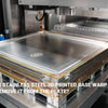
What Causes Warping and Corner Lifting on Large Industrial Parts?
Corner lifting ruins more large prints than any other single issue. Specifically, when you're printing 300mm+ parts in engineering materials, even perfectly leveled beds fail. Why? Because the real culprit isn't adhesion—it's thermal stress. As each layer cools, it contracts and pulls on the layers below. Subsequently, this creates enormous forces at the edges where parts meet the build plate. For industrial machinery components and large functional parts, this problem stops production cold.
The 3-Minute Warping Prevention Checklist:
- Build plate preparation: Clean with isopropyl alcohol, then apply fresh adhesive layer
- First layer settings: 110-120% extrusion width, 5-10°C hotter than normal layers
- Chamber control: Maintain 40-60°C ambient temperature for ABS/Nylon
- Support structures: Add 10-15mm brim or 5mm raft for maximum contact area
- Draft protection: Enable draft shield in slicer to block air currents
This five-step process addresses the fundamental challenge of eliminating warping on large prints before they fail.

To truly eliminate warping on large prints, you need to understand the physics at work. First, different materials have vastly different thermal expansion coefficients. For instance, ABS shrinks approximately 0.8% as it cools from 230°C to room temperature. On a 300mm part, that's 2.4mm of contraction trying to pull your print off the bed. Meanwhile, chamber temperature control becomes absolutely critical for rapid prototyping workflows where speed matters.
Additionally, build plate surface preparation makes or breaks adhesion. Textured PEI sheets work excellently for PETG and ABS, while garolite (G10) boards excel with Nylon. However, cleanliness matters more than material choice—even fingerprint oils reduce adhesion by 40%. Furthermore, applying thin layers of specialized adhesives like Magigoo creates a chemical bond that withstands thermal stress far better than mechanical grip alone.
Moreover, slicer settings dramatically affect warping tendency. Increasing first layer width to 120% creates a larger contact patch without overextrusion. Similarly, printing the first layer 5-10°C hotter than subsequent layers ensures maximum flow and adhesion. On the flip side, disable cooling fans entirely for the first 5-10 layers when working with high-shrinkage materials. The extra heat allows gradual temperature transition rather than thermal shock.
Finally, environmental control separates successful industrial printing from constant failures. Draft shields in your slicer create a protective barrier around the part, preventing cool air currents from creating temperature gradients. For ultimate control, enclosed printers with active heating maintain consistent 50-60°C chamber temperatures. This investment pays for itself after just a few saved prints on expensive engineering filaments used in electronics manufacturing applications.
Why Are Your Layers Weak Despite Accurate Dimensions?
Your parts look perfect but break along layer lines under stress. This frustrating scenario reveals a hidden truth: dimensional accuracy doesn't equal structural integrity. In fact, parts can measure perfectly while having only 60% of their potential strength. The problem lies in layer adhesion—specifically, whether adjacent layers truly fuse or merely stick together. For layer adhesion strong parts that meet structural requirements, you must optimize three interconnected variables: temperature, time, and cooling.
Immediate Strength Improvement Steps:
- Raise nozzle temperature by 10-15°C toward filament's upper limit
- Reduce print speed to 40-60mm/s for perimeters (structural areas)
- Lower cooling fan to 30% maximum for engineering materials
- Increase layer time by reducing print speed on small layers
- Test layer bonding using standardized tensile test specimens
These adjustments directly address engineering filament printing issues related to insufficient interlayer fusion.

Understanding layer bonding requires thinking about polymer science. When molten filament exits the nozzle, it must reheat the layer below enough for polymer chains to intermingle—a process called diffusion bonding. However, this happens only within a narrow temperature window. If the previous layer is too cool, you get mechanical adhesion only. Conversely, if both layers stay molten too long, you lose dimensional accuracy.
Temperature optimization starts with your material's glass transition temperature (Tg). For instance, ABS with Tg around 105°C needs nozzle temperatures of 230-250°C to ensure the layer below reaches at least 150°C when the new layer arrives. Therefore, printing at the manufacturer's minimum temperature (say, 230°C) often produces weak parts. Instead, test at 240°C and 250°C to find the sweet spot where strength improves without compromising surface quality.
Speed directly affects bonding time. When your nozzle races at 80-100mm/s, each point receives minimal heat transfer time. Consequently, reducing speed to 50mm/s for perimeters allows twice as much thermal energy to transfer into the previous layer. This single change often improves tensile strength by 20-30%. Furthermore, many slicers let you set different speeds for perimeters versus infill, allowing you to optimize strength without dramatically increasing print time.
Cooling fan management proves equally critical. While PLA requires active cooling for clean overhangs, materials like ABS, PETG, and Nylon actually suffer from too much cooling. Excessive airflow rapidly cools the fresh layer, preventing adequate diffusion bonding. For 3D printing plastics in demanding applications, start with fans at 20-30% maximum. Some industrial printers even use heated chambers instead of part cooling fans, allowing the entire print to cool slowly and evenly.
Testing remains essential for validation. Print standardized tensile test bars (ASTM D638 specimens) at different settings, then break them to measure actual strength. You'll quickly discover which parameter changes produce meaningful improvements versus which ones merely waste time. Moreover, this empirical approach builds a knowledge base specific to your exact printer, materials, and environment—something no general guide can provide.
How Do You Fix Inconsistent Extrusion in High-Flow Systems?
You upgraded to a high-flow hotend expecting faster prints. Instead, you're fixing under-extrusion industrial printer issues constantly. Flow inconsistency appears as gaps in top layers, weak infill, or dimensional inaccuracies. Additionally, you might see filament grinding, where the extruder chews into the filament without pushing it forward. These symptoms indicate your extrusion system is stressed beyond its capacity, creating bottlenecks that prevent reliable production.
Snippet Paragraph
High-Flow Troubleshooting Decision Tree:
Symptom: Inconsistent extrusion, visible gaps
- Check 1: Is filament dry? (If no → dry 4-6 hours at correct temp)
- Check 2: Is extruder gear marked/worn? (If yes → reduce tension or replace)
- Check 3: Is volumetric flow within hotend spec? (If no → reduce speed/layer height)
- Check 4: Is nozzle partially clogged? (If yes → cold pull or replace)
- Check 5: Is PTFE tube gap present? (If yes → trim tube and reseat)
This systematic approach identifies whether industrial 3D printer problems originate from material, mechanical, or thermal sources.

High-flow extrusion creates unique challenges because every component in the filament path faces increased stress. Starting at the extruder, higher back-pressure from faster melting requires more grip force. However, too much tension causes the drive gear to dig into the filament, creating notches that prevent forward movement. Paradoxically, the solution is often reducing tension, not increasing it. Most direct-drive extruders work optimally with just enough tension to prevent slippage—typically when you can spin the tensioner arm manually with moderate resistance.
Filament moisture becomes exponentially more problematic at high flow rates. When moisture-laden filament enters a 250°C+ hotend, water instantly vaporizes into steam. This creates back-pressure that fights against extrusion while also forming bubbles in the molten plastic. Subsequently, you see inconsistent flow, popping sounds, and surface defects. Engineering materials like Nylon absorb moisture readily from ambient air. Therefore, storing opened filament in dry boxes with desiccant and pre-drying for 4-6 hours before printing isn't optional—it's mandatory for reliable results.
Volumetric flow capacity represents your hotend's absolute limit. Every hotend has a maximum volumetric flow rate measured in mm³/s, determined by how fast it can melt filament. For example, a standard E3D V6 handles about 11mm³/s, while a Dragon High Flow reaches 24mm³/s. You calculate your required flow as: layer height × line width × print speed. Printing 0.3mm layers at 0.5mm width and 60mm/s requires 9mm³/s—within V6 capacity. However, increasing speed to 100mm/s requires 15mm³/s, exceeding the V6 and causing under-extrusion. Consequently, matching your ambitions to your hotend's specifications prevents impossible demands.
Partial clogs accumulate gradually from carbonized material buildup inside the nozzle. High-temperature printing accelerates this, especially when printing carbon fiber composites or materials with additives. Regular cold pulls using cleaning filament remove these deposits. Additionally, atomic method cleaning works excellently: heat to printing temperature, then cool to 90-110°C, and pull sharply to extract carbonized material attached to the solidified plug.
Finally, the PTFE tube gap in many hotends causes sneaky extrusion problems. The PTFE guides filament right to the melt zone. However, if it retracts even 0.5mm from the nozzle throat, molten plastic oozes into that gap and partially solidifies. This accumulating blob restricts flow unpredictably. The solution involves disassembling the hotend, thoroughly cleaning the heat break, and ensuring the PTFE tube butts firmly against the nozzle when reassembling. For high-temp FDM troubleshooting above 260°C, all-metal hotends eliminate PTFE entirely, preventing this degradation.
What Settings Eliminate Stringing on Production Runs?
Stringing turns aesthetically critical parts into scrap. Those thin plastic hairs stretching between features ruin surface finish and require extensive post-processing. For production runs where labor costs matter, preventing stringing saves both time and money. While basic advanced retraction settings help, a comprehensive anti-stringing strategy addresses multiple variables simultaneously. Moreover, different materials require different approaches—what works for PETG fails miserably with Nylon.
Complete Anti-Stringing System (Ranked by Impact):
- Filament dryness: Single biggest factor—dry thoroughly before blaming settings
- Retraction distance: Start at 5-7mm direct drive, 8-12mm Bowden, tune in 1mm increments
- Retraction speed: 40-60mm/s prevents grinding while being fast enough
- Nozzle temperature: Reduce by 5-10°C from optimal bonding temperature
- Coasting: Enable 0.2-0.5mm to depressurize nozzle before travel moves
- Wiping: Enable nozzle wipe on perimeter before travel moves
- Travel speed: Increase to 150-200mm/s to minimize oozing time
- Combing mode: Force travels within perimeters where possible
This hierarchy addresses production 3D printing failures related to surface finish systematically.

Moisture bears repeating because it's the #1 stringing cause that people blame on settings. Wet filament doesn't just ooze more—it fundamentally changes flow behavior. Steam bubbles create pressure inside the nozzle that forces material out even during retractions. Therefore, if you're fighting stringing with increasingly aggressive settings while using filament that's been sitting open for weeks, you're treating symptoms instead of the disease. Dry your filament in a dedicated dryer for 4-6 hours before printing, then immediately transfer to a dry box. This single step often eliminates 70% of stringing problems.
Retraction tuning requires understanding what's happening mechanically. When the printer retracts, it pulls molten plastic back up into the cooler zone of the hotend, reducing pressure and preventing ooze. However, too little retraction leaves pressure, causing strings. Conversely, too much retraction creates gaps in extrusion when printing resumes. Start conservatively (5mm for direct drive systems) and increase in 1mm increments while printing a stringing test tower. Note the height where stringing disappears—that's your optimal distance. Furthermore, retraction speed matters too; going too slow wastes time, while going too fast can grind filament. The 40-60mm/s range works well for most systems.
Temperature reduction trades a bit of layer strength for dramatically improved stringing resistance. If you've optimized temperature for bonding at 250°C but see stringing, try printing at 240°C. The cooler nozzle reduces plastic fluidity, making it less likely to ooze during travel moves. This works particularly well for final production runs where you've already validated strength at higher temperatures. Test parts confirm the temperature reduction doesn't compromise your strength requirements.
Advanced slicer settings provide additional control. Coasting stops extrusion slightly before completing a perimeter, allowing trapped pressure to dissipate as the last bit of filament finishes the line. Setting this to 0.3-0.5mm prevents over-extrusion at endpoints where strings typically start. Similarly, wipe moves drag the nozzle along the perimeter after completing a section, depositing any oozing material onto the part rather than stringing across gaps. Additionally, combing mode keeps travel moves within already-printed perimeters, so any strings land on infill rather than external surfaces.
For truly critical surface finish requirements, consider material alternatives. PETG strings notoriously while PLA barely strings at all. If your application allows material substitution, switching materials often solves stringing more effectively than endless setting optimization. Alternatively, using water-soluble support materials like PVA completely eliminates support-related surface imperfections since you dissolve rather than break away supports.
How Can You Remove Surface Defects and Vibration Patterns?
Ghosting, ringing, and layer lines plague otherwise-perfect prints. These repeating patterns appear as subtle waves on vertical surfaces, especially after sharp corners or direction changes. Unlike stringing or adhesion problems, these defects stem from mechanical vibrations in your printer's motion system. Consequently, solving them requires mechanical inspection and tuning rather than slicer adjustments alone. For precision applications where surface finish matters, eliminating these artifacts separates professional-grade parts from mediocre ones.
Vibration Elimination Protocol:
Mechanical Inspection (Do First):
- Tighten all frame bolts to manufacturer specifications
- Check belt tension (should resonate at 110Hz when plucked)
- Verify linear rails/rods show no play or binding
- Ensure printer sits on massive, rigid surface
Firmware Settings (Do Second):
- Reduce acceleration to 1000-1500mm/s² (from typical 3000mm/s²)
- Lower jerk/junction deviation to 8-10mm/s
- Enable input shaping if available (Klipper firmware)
- Set pressure advance/linear advance for material
Slicer Settings (Do Third):
- Reduce print speed to 40-60mm/s for outer perimeters
- Enable "outer perimeter first" for sharper corners
- Increase minimum layer time for small layers
This sequence addresses causes systematically rather than applying random fixes.
Understanding vibration requires recognizing that every printer has natural resonance frequencies. When rapid direction changes excite these frequencies, the motion system oscillates briefly. Since the print head continues moving during oscillation, it deposits material in a wavy pattern rather than a straight line. Therefore, the goal isn't eliminating all vibration—that's impossible—but rather preventing motion system changes from exciting resonant frequencies.
Belt tension dramatically affects print quality yet often gets overlooked. Loose belts allow the print head to lag behind commanded positions, creating positional errors. However, over-tightened belts stress bearings and create binding. Optimal tension produces a specific resonance frequency measurable with smartphone apps designed for 3D printer tuning. CoreXY printers typically need belts tuned to 110Hz, while Cartesian printers vary by model. Additionally, check that belt teeth engage pulleys fully along their entire width—even one misaligned tooth creates periodic defects.
Frame rigidity matters more than you'd expect. A printer bolted together loosely flexes during high accelerations, absorbing energy that should move the print head. Walk around your printer frame tightening every bolt and screw you can find. Moreover, printer placement affects vibration. A printer on a wobbly table transfers vibrations to its frame, amplifying resonance. Instead, place printers on concrete slabs, thick wood platforms, or dedicated vibration-dampening pads. The added mass and rigidity absorb kinetic energy rather than allowing it to resonate.
Acceleration and jerk settings control how rapidly the motion system changes speed and direction. High acceleration (3000-5000mm/s²) allows fast printing but creates large force spikes that excite resonances. Reducing acceleration to 1500mm/s² makes direction changes gentler, preventing resonance excitation. Similarly, jerk (or junction deviation) limits instantaneous velocity changes. Lower values create smoother motion paths at the cost of slightly longer print times. The performance trade-off is worth it for parts where surface finish matters.
Input shaping represents the cutting edge of vibration control. Available in Klipper firmware, this technique uses accelerometer data to measure your printer's exact resonance frequencies. Then, it algorithmically modifies motion commands to cancel out these resonances in real-time. The result is dramatically improved surface quality at higher speeds than traditional tuning allows. While setup requires running calibration routines and mounting an accelerometer, the investment pays dividends for high-volume production where both speed and quality matter.
Finally, print speed for outer perimeters directly affects visible surface quality. Inner perimeters and infill can print quickly since they're hidden. However, outer perimeters benefit from slower speeds (40-50mm/s) that reduce vibration excitation. Most slicers let you set different speeds for different features. Furthermore, enabling "outer perimeter first" prints the visible surface before inner structures, preventing inner perimeters from pushing the outer surface outward and creating bulges.
Conclusion
Industrial FDM printing troubleshooting separates profitable production from constant firefighting. While these five failure categories—warping, weak layers, extrusion inconsistency, stringing, and surface defects—cause 90% of production problems, each requires specific knowledge to solve. Moreover, solutions that work for hobbyist machines often fail at industrial scale with engineering materials and demanding geometries.
The path forward involves systematic diagnosis rather than random changes. Start with the quick-check tables provided for immediate issues. Then, dive deeper into the specific failure category affecting your production. Remember that filament dryness solves more problems than any other single intervention. Furthermore, maintaining detailed logs of successful print parameters builds institutional knowledge that prevents repeating past mistakes.
Success requires matching material properties to application requirements, equipment capabilities to production demands, and process parameters to part geometry. By applying the professional troubleshooting approaches detailed here, you'll reduce scrap rates, improve part quality, and maintain the production schedules that your business depends on. The investment in deeper understanding pays dividends through reliable, repeatable results that meet structural and aesthetic requirements consistently.
External Links Recommendation
[Industrial FDM printing troubleshooting][^1]
[Industrial 3D printer problems][^2]
[High-temp FDM troubleshooting][^3]
[Layer adhesion strong parts][^4]
---
[^1]: Explore this link to find expert solutions and tips for resolving common issues in Industrial FDM printing.
[^2]: This resource will help you understand and address the most frequent problems faced in Industrial 3D printing.
[^3]: Explore this link to discover effective solutions and tips for resolving common issues in high-temperature FDM printing.
[^4]: This resource will provide insights on techniques to enhance layer adhesion, ensuring your 3D prints are durable and reliable.


