
CNC Milling Cost Reduction: Can a 1mm Corner Radius Change Really Save You $10 Per Part?
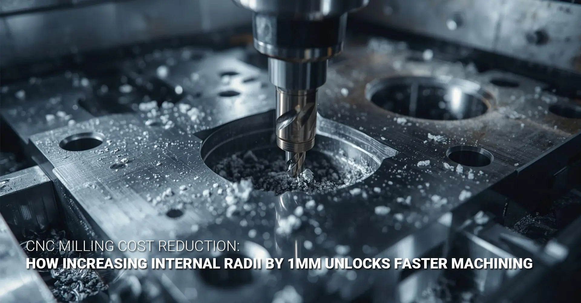
CNC Milling Cost Reduction: Can a 1mm Corner Radius Change Really Save You $10 Per Part?

Most designers never question their internal corners. They draw a pocket, leave the corners sharp, and move on. But that single habit is quietly adding dollars — sometimes $10 or more — to the cost of every single part that rolls off the machine.
The good news? The fix takes about three seconds in CAD.
Here's the short answer: Yes — increasing your internal corner radius by just 1mm can reduce your CNC milling costs by 30–50% per part. The reason is simple: a larger radius allows a larger cutting tool. A larger tool cuts faster, takes deeper passes, and removes material far more quickly. That one mouse click — changing R0.5 to R1.5 — can cut machining time in half.
| Corner Radius | Max Tool Diameter | Est. Machining Time (Bracket) | Approx. Part Cost |
|---|---|---|---|
| R0.5mm | 1/8" (3mm) | 4+ hours | $22.50 |
| R1.5mm | 1/4" (6mm) | ~2 hours | $15.30 |
| R3.0mm+ | 1/2" (12mm) | ~45 minutes | $9.80 |
So, where exactly does the money go — and how do you get it back? Let's walk through the mechanics, the math, and the practical steps you can take before your next drawing release.
Table of Contents
- Why Do Sharp Inside Corners Cost More in CNC Milling?
- What Does the "Corner Radius Cost Ladder" Actually Look Like?
- Beyond Machining Time — What Other Costs Does a Larger Radius Cut?
- When Does a Sharp Corner Actually Make Sense?
- Conclusion & Designer's Quick-Action Checklist
Why Do Sharp Inside Corners Cost More in CNC Milling?
Internal corner radius machining is one of the most misunderstood cost drivers in CNC part design. On the surface, a corner looks like a tiny detail. In reality, it controls the entire machining strategy for that feature.
The one-line answer: A sharp inside corner forces your machinist to use a tiny tool. Tiny tools are slow, fragile, and expensive to run — and that cost lands directly on your quote.
Here is what actually happens inside the machine. When a CNC end mill enters a pocket or cavity, the tool diameter must physically fit into the tightest corner. If your corner is R0.5mm, the largest possible tool is roughly 1mm in diameter — or, more practically, a 1/8" (3mm) end mill with a corner radius allowance. That constraint does not just affect the corner itself. It affects the entire pocket.
The machinist cannot switch to a large tool for the open areas and a small tool just for the corners. In most cases, the small tool must run the full feature — or the job requires multiple tool setups, each one adding time and cost.
Small tools carry three compounding penalties that drive up small tool machining cost:
- Chip evacuation: Smaller flutes clear chips less efficiently, requiring slower feed rates to avoid clogging and breakage.
- Depth of cut: A 3mm end mill can only take a shallow pass. More passes = more time.
- Rigidity: Small tools deflect under cutting forces. To maintain accuracy, the machinist must slow down — again.
The result? A feature that a 1/2" end mill could clear in 45 minutes takes a 1/8" end mill over four hours. Every minute on a CNC machine costs money. The math adds up fast.
Key insight: The corner radius does not just affect the corner — it sets the ceiling for the entire tool strategy on that feature.
What Does the "Corner Radius Cost Ladder" Actually Look Like?
The relationship between corner radius and cost is not a smooth curve. It is a step function — meaning costs drop sharply each time you can jump to the next standard tool size. Understanding this ladder is the heart of any cost saving design tips conversation with your machinist.
The three-step answer: At R0.5mm you are forced into the most expensive tier. At R1.5mm you unlock mid-range tooling. At R3mm and above, you access the fastest, most cost-effective cutting strategies available.
Let's put real numbers on this. Consider a mid-complexity aerospace bracket with multiple internal pockets:
Case A — R0.5mm corners (sharp inside corners CNC scenario):
- Required tool: 1/8" (3mm) end mill
- Estimated cycle time: 4+ hours
- Tool wear rate: High — small tools dull and break faster in tight corners
- Final part cost: $22.50
Case B — Same bracket, R1.5mm corners:
- Required tool: 1/4" (6mm) end mill
- Estimated cycle time: ~2 hours
- Tool wear rate: Moderate
- Final part cost: $15.30
- Savings: $7.20 per part — a 32% reduction
Case C — Same bracket, R3.0mm corners:
- Required tool: 1/2" (12mm) end mill
- Estimated cycle time: ~45 minutes
- Tool wear rate: Low
- Final part cost: ~$9.80
Now multiply that $7.20 saving by a production run of 500 parts. That is $3,600 saved from a design change that took three seconds.
The practical tool diameter selection guide for standard radii:
| Radius | Matching Standard Tool | Notes |
|---|---|---|
| R1.5mm | 1/4" / 6mm end mill | Most common "sweet spot" |
| R3.0mm | 1/2" / 12mm end mill | Significant time savings |
| R6.0mm | 1" / 25mm end mill | Best for large open pockets |
Pro tip: Always match your radius to a standard end mill size. A non-standard radius (e.g., R2.2mm) may require a custom-ground tool — adding cost and lead time.
This principle applies across industries. Whether you are producing automotive components or industrial machinery parts, the cost ladder works the same way.
Beyond Machining Time — What Other Costs Does a Larger Radius Cut?
Machining time is the biggest driver — but it is not the only one. The fillet radius economics go deeper than cycle time alone. Three additional cost areas quietly shrink when you move to a larger radius.
The three-savings summary: Larger radii mean fewer tool changes, longer tool life, and better surface finish — each one reducing cost in a different way.
1. Fewer Tool Changes = Less Machine Downtime
Every tool change stops the spindle. On a busy CNC machine, a single tool change takes 2–5 minutes — and complex parts with sharp corners may require 8–12 tool changes per cycle. Reducing that number by even two or three changes per part adds up quickly across a production run.
2. Longer Tool Life = Lower Consumable Cost
Small end mills used for design for manufacturing milling on tight corners wear faster and break more often. A 1/8" end mill cutting tight corners in aluminum may last 20–30 parts. A 1/4" end mill in the same material can run 80–100 parts. Replacement tooling is a real line item in your machinist's overhead — and it shows up in your quote.
This effect is even stronger in hard materials. If you are working with stainless steel CNC machining, the difference between small and large tooling is dramatic. Stainless work-hardens quickly. Small tools in stainless steel do not just wear faster — they can catastrophically fail mid-cut, scrapping an expensive workpiece.
3. Better Surface Finish = Fewer Secondary Operations
Larger tools leave a better surface finish on internal walls. A 1/8" end mill cutting tight corners often leaves visible chatter marks or scalloping. A 1/2" end mill produces a smoother wall in fewer passes. Fewer secondary operations — hand polishing, deburring, re-machining — means lower total cost and faster delivery.
Bottom line: Every point on the cost ladder you climb by increasing your radius saves money in at least three separate ways — not just one.
When Does a Sharp Corner Actually Make Sense?
This is the honest part of the conversation. Not every sharp corner is a design mistake. Some are genuinely required by function. The skill — and the real value of corner radius design guidelines — is knowing the difference between a corner that must be sharp and a corner that is sharp only out of habit.
One-line answer: A corner needs to be sharp only if it serves a specific functional purpose. Everything else is a candidate for a larger radius — and a lower cost.
Functional sharp corners — when sharp is truly required:
- Sealing surfaces: A gasket or O-ring seat may require a sharp corner for a leak-free seal.
- Mating features: A part that mates with another component may need a matching sharp corner for correct fit.
- Clearance requirements: Some assembly constraints leave no room for a fillet.
In these cases, the correct approach is to specify that corner only as sharp — and explicitly allow larger radii everywhere else. You can also consider electrical discharge machining (EDM) for that specific feature. EDM can cut true sharp internal corners without the tooling constraints of milling. It adds cost — but if the function truly demands it, it may be the right call. Learn more about the full range of CNC machining services available to handle these scenarios.
Habitual sharp corners — when sharp is just a default:
Most sharp corners on engineering drawings are not functional. They exist because:
- No one thought to add a radius
- The designer copied a previous drawing without review
- The CAD tool defaults to zero-radius corners
This is the "we've always done it this way" category — and it is where machining time reduction opportunities are hiding. A drawing note that says "BREAK ALL SHARP EDGES" is not the same as a designed radius. Great designers go further. They audit every internal corner before release and ask: "Does this corner need to be this small?"
How to communicate radius requirements clearly on your drawing:
- ✅ Add a general note: "ALL INTERNAL CORNERS R1.5 MINIMUM UNLESS OTHERWISE NOTED"
- ✅ Flag truly required sharp corners explicitly: "SHARP — FUNCTIONAL REQUIREMENT"
- ✅ Specify minimum radius matched to standard tooling, not an arbitrary number
- ❌ Do not leave corners unspecified — silence costs money
Remember: There is no such thing as a free sharp corner in CNC milling. Every 0.1mm of unnecessary radius reduction has a price — and you are paying it.
Conclusion
CNC milling cost reduction does not always require a major redesign. Sometimes it requires three seconds and one number change in CAD.
Here is what we covered:
- Sharp inside corners force small tools. Small tools are slow, fragile, and expensive.
- The cost ladder is a step function. Each jump to a larger standard tool unlocks major savings.
- Real numbers: R0.5mm → $22.50/part. R1.5mm → $15.30/part. A 32% reduction from one change.
- Savings go beyond cycle time — tool life, tool changes, and surface finish all improve.
- Not all sharp corners are bad — but most are habitual, not functional.
Designer's Quick-Action Checklist — Use Before Every Drawing Release
Before you send your next design for quoting, run through this list:
- [ ] Identify every internal pocket, cavity, and channel on the part
- [ ] Check the corner radius on each — is it specified, or defaulted to zero?
- [ ] Ask: "Is this corner functionally required to be sharp?" If not, increase it
- [ ] Match your radius to a standard tool size — R1.5, R3.0, or R6.0mm
- [ ] Add a drawing note: "ALL INTERNAL CORNERS R1.5 MIN UNLESS OTHERWISE NOTED"
- [ ] Flag truly sharp corners explicitly so your machinist knows they are intentional
- [ ] Request a DFM review if you are unsure — a good shop will tell you where the savings are
Ready to put this into practice? Send your design to our team for a free DFM review via our custom CNC milling service. We will identify every cost-saving radius opportunity before the job hits the machine.
Recommended External Resources
[CNC milling cost reduction][^1]
[internal corner radius machining][^2]
[corner radius design guidelines][^3]
[sharp inside corners CNC][^4]
[machining time reduction][^5]
[small tool machining cost][^6]
[^1]. A comprehensive design guide outlines practical strategies for reducing CNC machining expenses, focusing on material selection, geometry simplification, and the cost-saving benefits of incorporating corner reliefs in part designs.
[^2]. An expert technical tip explains how to optimize internal corner radii for CNC milling, highlighting why using non-standard radii can prevent tool chatter, improve surface finish, and significantly reduce overall machining time and costs.
[^3]. A comprehensive technical guide details how corner radius selection impacts CNC machining quality and efficiency, providing specific recommended minimum radius values based on feature depth to optimize both performance and budget.
[^4]. An in-depth resource explains the challenges of machining sharp internal corners and offers practical design solutions, including the use of fillets, dogbone reliefs, and alternative processes like EDM for specialized requirements.
[^5]. A strategic engineering guide provides actionable design tips for reducing CNC machining time and lead times, emphasizing the importance of simplifying part geometry, minimizing setups, and standardizing tooling to enhance manufacturing efficiency.
[^6]. An insightful analysis explores the total cost of ownership in CNC tooling, explaining how the performance of small-diameter and high-precision tools impacts overall machining economics, including machine utilization, maintenance, and hidden operational expenses.