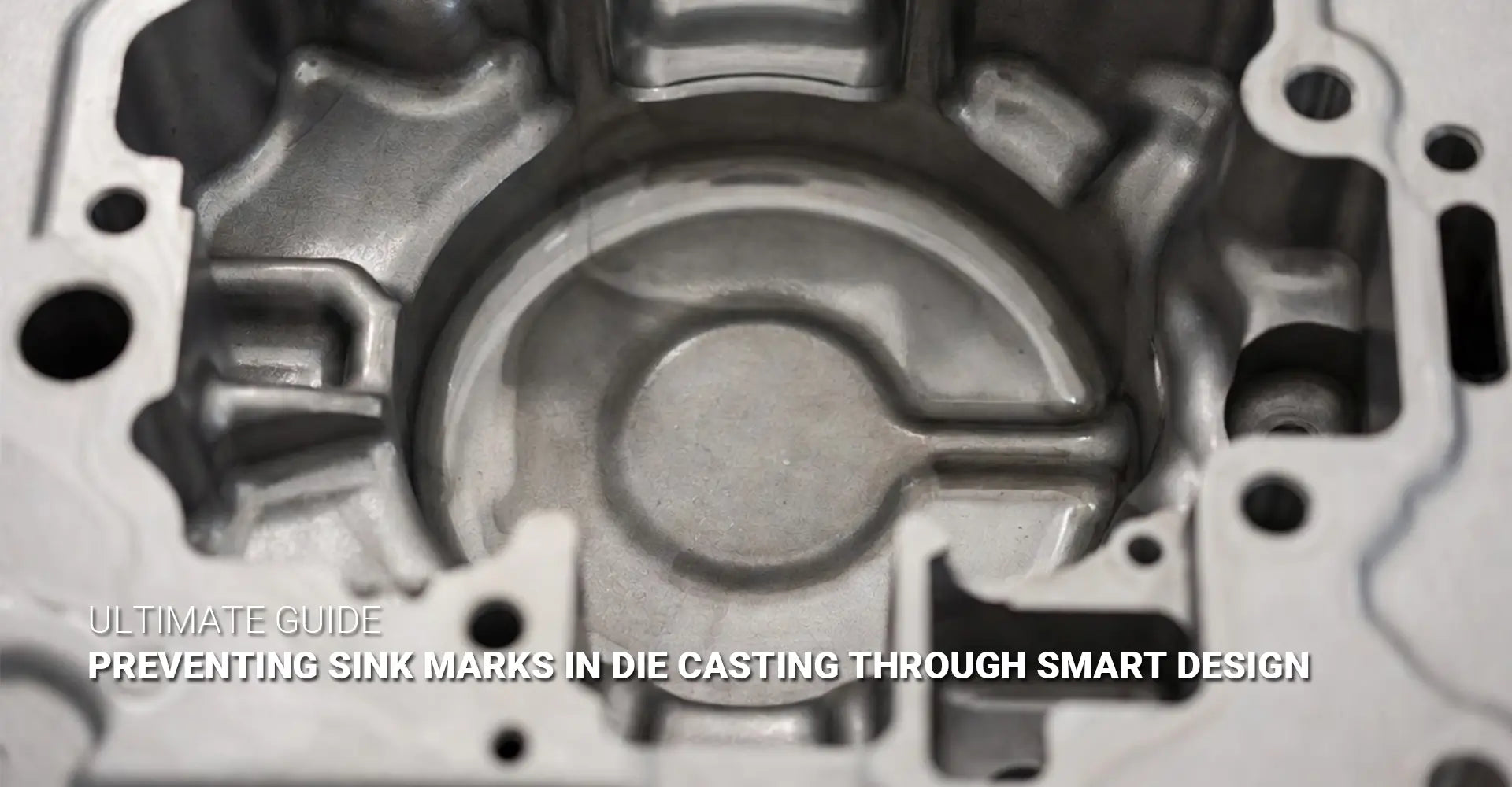
How Do You Prevent Sink Marks in Die Casting Parts?
How Do You Prevent Sink Marks in Die Casting Parts?

Sink marks ruin the appearance of die casting parts and drive up scrap rates. Moreover, they frustrate engineers who spent weeks perfecting their CAD models, only to see surface depressions appear after the first production run. Consequently, understanding how to prevent these defects is crucial for anyone working with die casting.
Quick Answer: Stop Sink Marks Before They Start
| Design Rule | Action | Why It Matters |
|---|---|---|
| Wall Thickness | Keep uniform at 2–4mm | Prevents uneven cooling |
| Rib Design | Use 0.6:1 ratio (rib:wall) | Reduces localized shrinkage |
| Hollowing Strategy | Remove thick zones safely | Eliminates slow-cooling areas |
| Gate Placement | Position away from thick walls | Controls solidification order |
The good news? Preventing sink marks in die casting starts with smart design choices, not expensive fixes on the production floor. By following proven design rules—especially maintaining uniform wall thickness and proper rib proportions—you can eliminate most sink mark issues before cutting steel for your mold.
Table of Contents
- What Are Sink Marks and Why Do They Appear on Die Casting Surfaces?
- Why Does Uneven Wall Thickness Cause Sink Marks in Die Castings?
- How Does the 0.6:1 Rib-to-Wall Thickness Ratio Prevent Surface Defects?
- What Design Strategies Remove Thick Zones Without Weakening the Part?
- Conclusion
What Are Sink Marks and Why Do They Appear on Die Casting Surfaces?
A sink mark is a surface depression that appears on die casting parts when internal material shrinks during cooling. Furthermore, this defect shows up as a visible dent or dimple, typically located directly above thick sections, ribs, or bosses.
Here's the simple science: When molten metal fills the die, the outer surface touching the cold mold wall solidifies first, creating a thin shell. Meanwhile, the material inside remains liquid and continues to cool. As this interior metal shrinks, it pulls the already-solid outer surface inward, creating the characteristic depression we call a sink mark.
Understanding sink marks die casting causes requires looking at thermal behavior. Different metals shrink at different rates—aluminum alloys typically shrink 3.5–8.5% by volume, while zinc alloys shrink around 0.6%. Therefore, wherever you have uneven cooling or thickness variations, you create the perfect conditions for sink marks to form.
Unlike porosity (which involves trapped gas) or cold shuts (which result from premature solidification during filling), sink marks are purely a shrinkage issue. For instance, imagine a cosmetic housing for electronics manufacturing with a thick mounting boss on the back. Even though the boss is hidden, the sink mark appears on the visible front surface, ruining the part's appearance and making it unusable for high-quality applications.
Why Does Uneven Wall Thickness Cause Sink Marks in Die Castings
Thick sections cool significantly slower than thin sections, creating the fundamental cause of sink marks. In fact, this temperature difference drives nearly every surface defect problem in die casting.
The rule is straightforward: Wherever you have a thickness change greater than 15–20%, you risk creating a visible sink mark. Consequently, maintaining uniform wall thickness isn't just a suggestion—it's the foundation of quality die casting design.

Let's walk through exactly what happens during cooling. First, molten metal enters the die cavity and immediately contacts the steel mold surface. Within milliseconds, a solid skin forms on all surfaces exposed to the mold. Then, solidification progresses from the surface toward the center of each wall section.
In uniform-thickness areas, this progression happens evenly and predictably. However, thick zones act as "hot spots" that lag behind the rest of the part. While thin walls might solidify in 2–3 seconds, a thick boss could take 8–10 seconds or longer. During this extended cooling period, the material continues shrinking, and since the surface is already solid, the only direction it can shrink is inward.
Following die casting wall thickness design standards helps avoid this problem. Typical targets include:
- Aluminum alloys: 2–3mm for most sections
- Zinc alloys: 1.5–2.5mm for standard parts
- Magnesium alloys: 2–4mm depending on part size
When designing parts for automotive or industrial machinery applications, these targets become even more critical. Additionally, you should aim for thickness transitions no steeper than 3:1 ratio over any given distance, with generous fillet radii (typically 0.5–1.5mm) to smooth the thermal gradient.
How Does the 0.6:1 Rib-to-Wall Thickness Ratio Prevent Surface Defects?
Ribs add strength without adding weight, but only when designed correctly. Otherwise, they become the primary source of sink marks on your parts.
The critical formula: Rib thickness should equal approximately 60% of the nominal wall thickness. This rib to wall thickness ratio die casting ensures that ribs cool at nearly the same rate as the surrounding walls, preventing the thermal imbalance that causes sink marks.
Why does rib thickness matter so much? Thicker ribs create concentrated thermal mass that delays solidification. For example, if your wall is 3mm thick and you add a 3mm-thick rib, that intersection point effectively becomes 6mm thick—double the surrounding material. Consequently, it cools at roughly one-quarter the rate, virtually guaranteeing a sink mark on the opposite surface.
Here's a practical calculation example following die casting rib design rules:
- Nominal wall thickness: 3.0mm
- Maximum rib thickness: 3.0mm × 0.6 = 1.8mm
- Recommended rib thickness: 1.5–1.8mm
- Rib height: Limited by part requirements, but typically 2–5× wall thickness
- Rib spacing: 3–5× wall thickness (9–15mm in this example)
Additionally, proper rib design includes several other critical details. First, use generous fillet radii at the rib base—typically 0.3–0.5mm radius—to avoid stress concentrations and improve metal flow. Second, apply draft angles of 1–3° to both sides of the rib for easy part ejection. Third, when possible, position ribs on non-cosmetic surfaces (the B-side of the part) to hide any minor surface effects.
Strategic rib placement makes a significant difference. Instead of one thick rib, use multiple thinner ribs spaced appropriately. Rather than continuous ribs, consider interrupted or staggered patterns that reduce local thermal mass. These approaches help you avoid surface defects die casting while maintaining structural performance.
What Design Strategies Remove Thick Zones Without Weakening the Part?
Sometimes your design legitimately needs structural mass in specific locations. However, you don't have to leave that material solid—hollowing it out provides the answer.
Core principle: Pockets, cavities, and strategic material removal maintain strength while keeping effective wall thickness consistent throughout the part. Therefore, you can meet structural requirements and cosmetic specifications simultaneously.
Hollowing works best in these common scenarios:
- Mounting bosses: Instead of solid cylinders, create hollow tubes with 2–3mm walls
- Corner junctions: Remove material from thick intersections where three walls meet
- Structural posts: Add internal cavities with cross-ribs for support
- Heavy sections: Replace bulk material with thin-walled box structures
When implementing hollow features, maintain minimum wall thickness of 1.5–2mm to prevent collapse during filling or ejection. Furthermore, ensure adequate draft angles (typically 2–3° for deep cavities) and generous corner radii (minimum 0.5mm) to promote smooth metal flow and avoid air traps.
The trade-offs are worth understanding. Hollowing increases die complexity because you need additional slides, cores, or collapsible features to form the internal cavities. Consequently, tooling costs rise by 15–30% in many cases. However, the benefits often outweigh these costs: dramatically improved surface finish, reduced cycle times (faster cooling), lower scrap rates, and decreased part weight.
Gate location becomes especially important for hollow designs. Avoid placing gates where trapped air could accumulate during filling—this leads to porosity issues that compromise structural integrity. Instead, position gates to allow air to escape naturally toward vents. For complex hollow geometries, consider using overflow wells (small cavities that capture initial cold metal and air) to ensure complete filling.
Before committing to expensive tooling, validate your design using simulation software. Modern casting simulation tools can model filling time, temperature distribution, and solidification sequence, helping you identify potential problems. These programs predict shrinkage porosity die casting and sink mark locations with remarkable accuracy, allowing design iterations in hours rather than weeks.
Working collaboratively with your die caster during the design review phase pays significant dividends. Experienced die casters can suggest modifications—gate repositioning, local wall thickness adjustments, or alternative reinforcement strategies—that preserve your design intent while eliminating defect risks. This partnership approach, combined with following die casting design guidelines, ensures your parts meet specifications on the first production run.
Conclusion
Preventing sink marks comes down to one fundamental principle: uniformity is everything. Whether you're managing wall thickness, proportioning ribs, or controlling thermal behavior, consistent design prevents the cooling imbalances that cause surface depressions.
Treat die casting like injection molding by applying the same rigorous discipline to wall uniformity, draft angles, and fillet radii. Additionally, leverage simulation tools during the design phase—they reveal problems when changes cost pennies, not thousands of dollars in tooling modifications.
Remember these key rules:
- Maintain uniform wall thickness (2–4mm for most aluminum parts)
- Size ribs at 60% of wall thickness maximum
- Hollow out thick zones using pockets and cavities
- Position gates strategically to control solidification sequence
- Work with your die caster early and often
Most importantly, understand that preventing sink marks starts on the CAD screen, not the shop floor. By following these proven design practices, your parts will meet appearance specifications and quality standards from the very first shot. Consequently, you'll reduce scrap, accelerate time-to-market, and build a reputation for delivering defect-free components.
Recommended Resources
[sink marks die casting causes][^1]
[die casting rib design rules][^2]
[rib to wall thickness ratio die casting][^3]
[avoid surface defects die casting][^4]
[shrinkage porosity die casting][^5]
[die casting cooling and solidification][^6]
---
[^1]: Understanding the causes of sink marks can help improve product quality and reduce defects in die casting.
[^2]: Learning rib design rules is crucial for enhancing strength and reducing weight in die cast components.
[^3]: Understanding this ratio is crucial for optimizing the strength and performance of die-cast components.
[^4]: Exploring techniques to prevent surface defects can significantly enhance the quality and durability of your die-cast products.
[^5]: Understanding shrinkage porosity is crucial for improving die casting quality and reducing defects. Explore this link for in-depth insights.
[^6]: Learn about the cooling and solidification process in die casting to enhance your manufacturing techniques and product quality.


