How Can You Reduce Sheet Metal Thickness by 20% Without Losing Stiffness?
How Can You Reduce Sheet Metal Thickness by 20% Without Losing Stiffness?

Rising steel prices are squeezing budgets across manufacturing. At the same time, engineers face constant pressure to maintain part performance while cutting costs. The good news? You don't always need thicker material to build stronger, stiffer parts. By using smart geometry instead of extra millimeters, you can save material, reduce weight, and keep your panels rigid.
Key Takeaways at a Glance
| Challenge | Solution | Benefit |
|---|---|---|
| Rising material costs | Embossed ribs and flanges | 10–25% thickness reduction |
| Panel buckling | Strategic rib placement | Increased stiffness without added weight |
| Warping and springback | Proper flange design | Better dimensional control |
| High BOM cost | Lightweighting strategy | Up to 20% material cost savings |
This guide will walk you through proven techniques to stiffen thinner sheet metal using geometry instead of thickness. Whether you're working on industrial machinery enclosures or automotive components, these methods apply across industries. Additionally, you'll learn practical design rules, manufacturing considerations, and validation steps to implement lightweighting successfully.
Table of Contents
- Why Are Sheet Metal Prices Climbing and What Can Designers Do?
- What Is the Difference Between Stiffness and Strength in Sheet Metal?
- How Does Embossing Increase Stiffness Without Adding Weight?
- How Do Flanges and Edge Features Prevent Panel Buckling?
- Conclusion
Why Are Sheet Metal Prices Climbing and What Can Designers Do?
Steel and aluminum prices have jumped dramatically over the past few years. Furthermore, supply chain disruptions and energy costs continue to push material expenses higher. For many manufacturers, raw material now represents 40–60% of total part cost, making every millimeter of thickness a target for savings.
Quick Summary: Material cost now dominates the bill of materials in sheet metal fabrication. As a result, thickness reduction has become one of the fastest levers for sheet metal BOM cost optimization.
The traditional response—"just make it thicker"—no longer works when budgets are tight and weight matters. Instead, designers are turning to sheet metal lightweighting strategies that use geometry to replace mass. This approach maintains structural performance while cutting material usage by 10–25% in typical applications.
Several factors drive this shift. First, global steel demand remains high while production capacity struggles to keep pace. Second, energy-intensive manufacturing processes add cost at every stage. Third, transportation and handling expenses increase with part weight, especially in high-volume production. Therefore, lightweighting delivers benefits beyond raw material savings.
Designers can respond by rethinking panel geometry. Rather than specifying thicker gauge sheet metals, you can add ribs, beads, or flanges to stiffen the same part. This strategy requires close collaboration with manufacturing partners, but the payoff is substantial. Moreover, many companies discover that lightweighted designs are easier to handle, ship, and assemble.
What Is the Difference Between Stiffness and Strength in Sheet Metal?
Many engineers confuse stiffness with strength. However, these properties behave very differently, and understanding the distinction is critical for successful lightweighting.
Simple Rule: Strength tells you the maximum load before the material fails. In contrast, stiffness measures how much the part bends under a given load.
Strength depends mostly on material properties and thickness. If you need higher strength, you typically choose a higher-grade steel or add thickness. On the other hand, stiffness depends heavily on geometry—specifically, the second moment of area (also called area moment of inertia).
This is why a thin I-beam can support heavy loads without bending much. The shape moves material away from the neutral axis, dramatically increasing the second moment of area. Similarly, a thin sheet metal panel with ribs or flanges can outperform a thicker flat panel in bending stiffness.
The formula for bending stiffness is proportional to E × I, where E is the material's modulus of elasticity and I is the second moment of area. Since E is fixed for a given material, increasing I through geometry is the key to boosting stiffness. Consequently, small geometric changes can replace millimeters of thickness.
For example, adding a single embossed rib can increase local stiffness by 200–400%, depending on rib depth and orientation. Meanwhile, a hemmed edge flange can double or triple edge stiffness with minimal weight addition. Therefore, sheet metal stiffness optimization focuses on maximizing I rather than simply adding mass.
This principle applies across applications. Whether you're designing covers for industrial machinery, body panels for automotive use, or enclosures for electronics, geometry-driven stiffness improvements offer a path to lighter, cheaper parts without sacrificing performance.
How Does Embossing Increase Stiffness Without Adding Weight?
Embossing creates local stiffness by forming ribs, beads, or corrugations directly into the sheet. Unlike adding brackets or doubler plates, embossing uses the existing material more efficiently. As a result, you gain stiffness without adding weight.
Embossing Types:
- Linear ribs: Best for resisting bending in one direction
- Dimples and beads: Provide broad-area stiffening across a panel
- Corrugated patterns: Ideal for large, flat surfaces that need resistance to oil canning

Effective sheet metal embossing design starts with understanding load paths. First, identify where the panel will experience the highest deflection or vibration. Then, orient ribs perpendicular to the main bending direction. This alignment maximizes stiffness improvement.
Design rules for embossing include:
- Depth: Aim for emboss depth between 3–6 times the material thickness. Shallow embosses provide minimal benefit, while overly deep features risk cracking or excessive springback.
- Width: Keep rib width proportional to depth. Narrow, deep ribs concentrate stress and may fail during forming. A width-to-depth ratio of 2:1 to 4:1 works well in most cases.
- Spacing: Space ribs at least 5–10 times the material thickness apart. Closer spacing can cause interference during forming and doesn't add much stiffness.
- Radii: Use generous radii at the base and top of embossed features. Sharp corners invite cracking and make tooling more expensive.
Common mistakes include placing ribs too close together, using inconsistent rib depth across the panel, and ignoring material grain direction. Additionally, ribs that run parallel to the bending load do little to improve stiffness. Therefore, always align features with the load path.
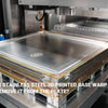
Case Study: An industrial machinery enclosure door originally used 2.0 mm cold-rolled steel. By adding three linear ribs (4 mm deep, spaced 80 mm apart), the design team reduced thickness to 1.5 mm. The new door passed the same static load and vibration tests while cutting material cost by 18%. Furthermore, the lighter door reduced hinge loads and improved ease of handling during assembly.
This approach works especially well for thin gauge sheet metal design. When working with gauges below 1.5 mm, embossing becomes almost mandatory to prevent oil canning and buckling. Moreover, combining ribs with strategic flange placement delivers even greater stiffness gains.
For complex geometries, consider using forming simulation software. Tools like AutoForm or PAM-STAMP can predict springback, thinning, and potential cracks before you cut tooling. This step is especially important when pushing the limits of thin gauge strength improvement.
When collaborating with sheet metal fabrication partners, share your embossing intent early. Suppliers can suggest rib profiles from their standard tooling library, reducing tooling cost and lead time. Additionally, they can flag manufacturability issues like excessive draw depth or tight radii that may cause scrap.
How Do Flanges and Edge Features Prevent Panel Buckling?
Open edges are the weakest areas of any flat panel. Without support, edges bend easily under load, leading to oil canning, vibration, and visible deflection. Fortunately, flanges and edge features provide structural reinforcement with minimal material addition.
Flange Benefits:
- Doubles or triples edge stiffness
- Reduces oil canning and vibration
- Adds minimal weight compared to doubler plates
- Requires simple tooling in most cases
A flange works by moving material away from the panel's neutral axis, increasing the second moment of area along the edge. Even a small flange—just 10–15 mm high—can dramatically improve the stiffness to weight ratio sheet metal panels achieve.
Design Guidelines for Flanges:
- Height: Taller flanges provide more stiffness, but they also increase forming difficulty and springback. For most applications, flange heights of 8–20 mm work well. Consequently, you gain stiffness without excessive tooling complexity.
- Angle: 90-degree flanges are the most common and easiest to form. However, angled flanges (75–85 degrees) can reduce springback in high-strength materials. Additionally, return flanges (flanges bent back toward the panel) offer even higher stiffness.
- Direction: Orient flanges perpendicular to the main bending direction for maximum effect. Flanges that run parallel to the bend contribute less to stiffness.
- Transitions: Use smooth transitions where flanges meet the flat panel. Sharp corners concentrate stress and can initiate cracks, especially in higher-strength sheet metals.
Preventing Warping and Distortion:
When adding flanges, warping can occur due to residual stress from forming. To minimize this risk:
- Balance flanges on both sides of the panel when possible
- Use relief cuts or notches at corners to reduce stress concentration
- Avoid combining very tall flanges with very thin material
- Consider stress-relief annealing for critical parts
For automotive applications, hemmed flanges are common on door panels and hoods. Hemming folds the edge completely back on itself, creating a smooth, safe edge with excellent stiffness. However, hemming requires two forming operations and careful control of springback.
Return flanges and joggle flanges are useful when you need to attach panels or create mounting surfaces. These features add local stiffness while serving a functional purpose. Moreover, they can eliminate the need for separate brackets or fasteners, reducing part count and assembly time.
DFM Considerations:
When working with press brakes or progressive dies, consider the following:
- Ensure sufficient clearance for tooling access
- Avoid flanges in areas with tight radii or complex geometry
- Check that flange height doesn't exceed press capacity
- Verify that the material can handle the required bend without cracking
Early collaboration with your sheet metal fabrication partner helps catch these issues before tooling is cut. Additionally, suppliers can suggest standard flange profiles that work well with their equipment, reducing cost and lead time.
Combining flanges with sheet metal structural ribs creates a powerful stiffness strategy. For example, a large panel might use ribs in the center to resist bending and flanges along the edges to prevent buckling. This combination allows you to maximize sheet metal material saving while maintaining structural performance.
For prototyping and validation, consider using rapid prototyping services to test your lightweighted design before committing to production tooling. Physical prototypes reveal issues like noise, vibration, and unexpected deflection that simulation may miss.
Conclusion
Sheet metal lightweighting is not just about reducing thickness—it requires a systematic approach to geometry optimization, manufacturing collaboration, and performance validation. By combining embossed ribs for directional stiffness and flanges for edge stability, you can achieve material savings of 10–25% in many applications.
The key takeaways are straightforward. First, understand that stiffness depends more on geometry than thickness. Second, use embossing and flanges to increase the second moment of area without adding weight. Third, collaborate early with your manufacturing partner to ensure the design is producible. Finally, validate your lightweighted design through calculation, simulation, or physical testing before scaling to production.
Start with one pilot part. Measure both cost savings and performance carefully. Document what works and what doesn't. Over time, you'll build a library of proven lightweighting techniques that apply across your product line.
As material costs continue to rise, designers who master geometry-driven stiffness will deliver better parts at lower cost. Whether you're working on industrial machinery, automotive components, or other sheet metal fabrication projects, these principles offer a path forward.
Recommended External Resources
[Sheet metal lightweighting][^1]
[Reduce sheet metal material cost][^2]
[sheet metal stiffness optimization][^3]
[sheet metal embossing design][^4]
[BOM cost optimization][^5]
[Stiffening ribs sheet metal][^6]
---
[^1]: Exploring this resource will provide insights into how lightweighting can enhance performance and reduce costs.
[^2]: This link will offer strategies and techniques to minimize costs while maintaining quality in sheet metal production.
[^3]: Explore this link to discover effective techniques and strategies for enhancing the stiffness of sheet metal, crucial for structural integrity.
[^4]: This resource will provide insights into innovative design approaches for sheet metal embossing, improving both functionality and aesthetics.
[^5]: Explore this link to discover effective strategies for reducing costs in your sheet metal BOM.
[^6]: Learn how stiffening ribs enhance structural integrity and performance in sheet metal applications.


