How Does Poor RTCP Calibration Destroy Your 5-Axis Machining Accuracy?
How Does Poor RTCP Calibration Destroy Your 5-Axis Machining Accuracy?

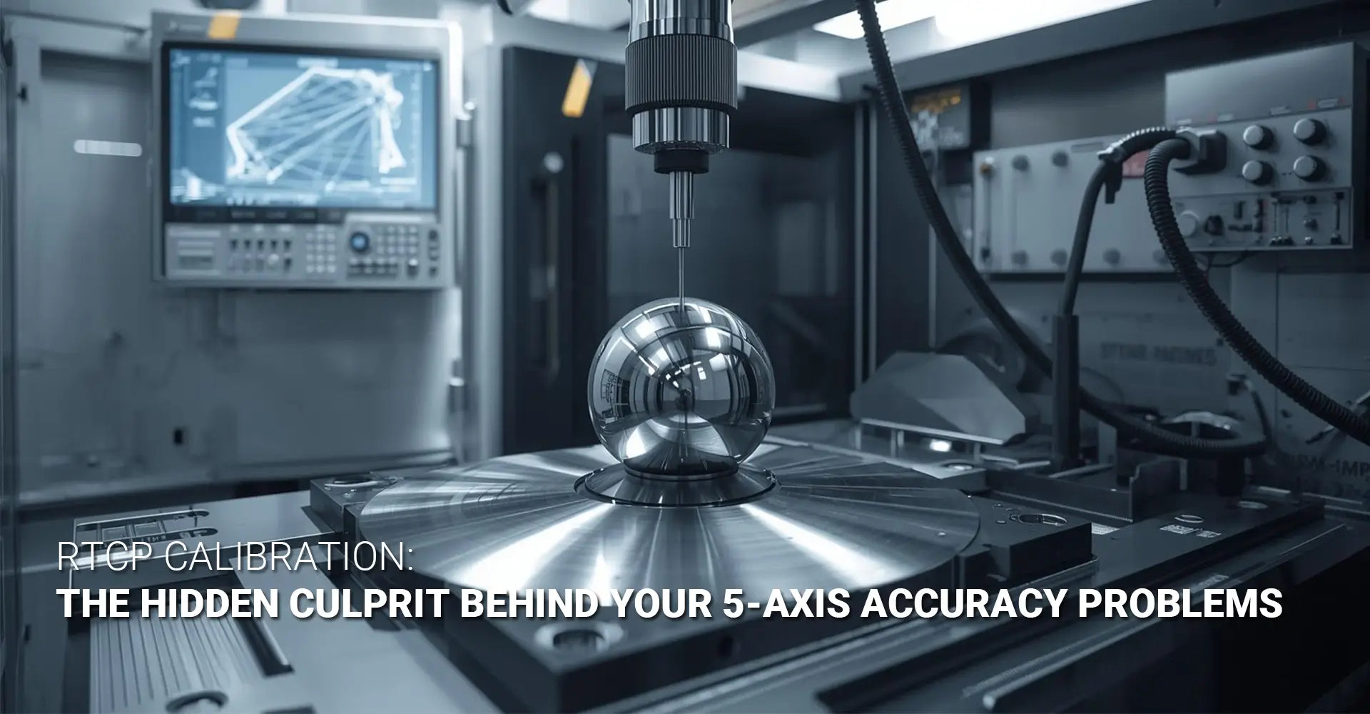
When your 5-axis CNC machine produces parts with mysterious errors that persist despite perfect programming, the problem often hides in plain sight. RTCP calibration—the geometric relationship defining how your rotary axes interact with your cutting tool—directly determines whether your machine can deliver the precision you expect. Consequently, even minor calibration errors create tapered holes, mismatched contours, and costly scrap parts that frustrate even experienced machinists.
Quick Answer: What You Need to Know Right Now
RTCP (Rotation Around Tool Center Point) calibration defines the precise geometric relationship between your rotary axes and tool tip position. When this calibration drifts or was never properly set, your programmed tool path deviates from actual cutting positions. As a result, you'll see tapered holes when drilling at angles, mismatched contours from different orientations, and surface finish problems during simultaneous 5-axis motion—all symptoms that waste time and materials.
| Problem Sign | Root Cause | Typical Deviation |
|---|---|---|
| Tapered/elliptical holes | Rotary centerline offset | 0.05-0.2mm |
| Contour mismatches | Incorrect pivot point | 0.03-0.15mm |
| Surface finish degradation | Combined axis error | Visual striping |
| Transition gouging | Poor kinematic model | 0.02-0.10mm |
Why This Matters for Your Shop
Understanding RTCP calibration transforms your approach to CNC machining service quality control. Moreover, this knowledge helps you diagnose problems faster, reduce scrap rates, and maintain the consistent surface finish your customers expect. Therefore, investing time in proper calibration pays immediate dividends in both part quality and production efficiency.
Table of Contents
- What Is RTCP Calibration and Why Does It Matter?
- How Can You Identify RTCP Calibration Problems?
- What Equipment and Steps Are Needed for Proper Calibration?
- How Do You Maintain Long-Term 5-Axis Precision?
What Is RTCP Calibration and Why Does It Matter?
Understanding the Core Concept
5 axis CNC RTCP calibration establishes the mathematical model that describes how your machine's rotary axes physically relate to each other and to your cutting tool. Essentially, your CNC control needs to know exactly where the rotary axis centerlines intersect in three-dimensional space. Without this information, the control cannot accurately compensate for tool tip movement when rotary axes change position.
The Reality Behind the Name
Different control manufacturers use different terminology for the identical concept. RTCP (Rotation Around Tool Center Point) appears commonly with European controls and Heidenhain systems. Similarly, TCPM (Tool Center Point Management) describes Siemens implementations, while TCPC (Tool Center Point Control) identifies Fanuc and Japanese machine builder conventions. Nevertheless, all three terms describe the same critical function: keeping your tool tip exactly where your program specifies, regardless of rotary axis movement.
How the Kinematic Model Works
Your machine control uses forward and inverse kinematics to translate your programmed XYZ coordinates into the actual linear and rotary axis positions needed. However, this calculation depends entirely on accurate geometric parameters describing your machine's physical structure. The five-axis machine tool center point represents the theoretical pivot point where both rotary axes intersect, and any error in defining this location propagates through every calculation.
Think of it this way: if your control believes the rotary axes intersect 2mm away from their actual intersection point, every tool path gets shifted by that amount. Furthermore, this error changes direction as the rotary axes move, creating the complex error patterns you see on finished parts.
Factory Calibration Limitations
Many shops assume their machine arrived with perfect calibration and never verify it. Unfortunately, this assumption causes problems. Factory calibration provides a starting baseline, but several factors degrade accuracy over time:
- Mechanical wear in rotary axis bearings and gear trains shifts the actual centerline positions
- Thermal expansion changes structural geometry as the machine warms up
- Minor collisions or impacts can shift rotary axis relationships without obvious damage
- Transportation and installation stresses may alter the machine geometry from factory conditions
Therefore, treating factory calibration as permanent guarantees eventual accuracy problems.
The Volumetric Accuracy Connection
Volumetric accuracy 5-axis describes your machine's ability to position the tool tip accurately anywhere within its working envelope. Specifically, this measurement captures the combined effect of all linear and rotary axis errors. Poor RTCP calibration directly degrades volumetric accuracy because the rotary axis errors don't stay constant—they vary with position and orientation. Consequently, a machine might show excellent linear axis accuracy but still produce bad parts due to rotary axis calibration errors.
How Can You Identify RTCP Calibration Problems?
Recognizing Part Symptoms
RTCP calibration errors create distinctive patterns on finished parts that differentiate them from other machining problems. Most importantly, these errors remain consistent and repeatable across multiple parts, which helps you distinguish calibration issues from random factors like tool wear or thermal drift.
Tapered or elliptical holes represent the most common symptom. When you drill or bore at an angle using rotary axis positioning, calibration errors cause the tool to follow a slightly curved path instead of a straight line. As a result, your hole becomes tapered or oval-shaped even though your program specifies a perfect cylinder.
Mismatched contours appear when you machine the same feature from different orientations. For example, if you mill a boss from one angle in operation 1, then rotate the part and blend into the same feature from operation 2, you'll see a visible step or mismatch at the transition. This happens because each rotary position has different compensation errors.
Surface Quality Indicators
The surface finish on your parts often reveals calibration problems before dimensional issues become obvious. During simultaneous 5-axis motion, poor calibration creates small velocity variations and direction changes that show up as surface ripples or "chatter" marks. However, these marks appear even with sharp tools and appropriate feeds and speeds, indicating the problem lies in machine geometry rather than cutting parameters.

Diagnostic Testing Methods
Quick probe verification provides the fastest calibration check. Mount a precision sphere (calibrated to ±0.0025mm or better) somewhere in your work envelope. Then, probe the sphere from multiple rotary positions—at minimum, test at A0/C0, A90/C0, A0/C90, and A90/C90 if you have a trunnion-style machine. Additionally, record the measured sphere center coordinates from each position.
If your calibration is correct, all measurements should report identical XYZ coordinates for the sphere center, within your probe's repeatability (typically ±0.005mm). However, if the measured positions vary by more than 0.01mm, you have calibration errors requiring correction.
Ballbar testing offers more comprehensive diagnosis. A ballbar system measures circular interpolation accuracy by mounting a telescoping bar between the spindle and a fixed ball on the table. Then, the machine executes circular tool paths at various compound angles while the ballbar records actual position deviations. The resulting plots reveal specific error patterns that identify rotary axis centerline misalignment, thermal effects, and backlash issues.
Distinguishing Calibration from Other Issues
Not every accuracy problem stems from calibration. Therefore, understanding what RTCP errors do not cause helps you diagnose correctly:
- Random variations between parts suggest thermal issues, tool wear, or work-holding problems rather than calibration
- Errors only in 3-axis mode point to linear axis problems, not rotary calibration
- Errors that change with tool length indicate tool measurement problems, not kinematic errors
- Progressive errors over time suggest thermal growth rather than static calibration offset
Conversely, if your errors remain consistent across parts, change predictably with rotary position, and affect simultaneous 5-axis motion specifically, you're almost certainly dealing with calibration issues.
What Equipment and Steps Are Needed for Proper Calibration?
Required Hardware and Software
Successful TCPM calibration procedure implementation requires specific equipment beyond your standard machine tools. First, you need a precision calibration sphere certified to ±0.0025mm or better, typically 25mm to 50mm in diameter. This sphere serves as your reference point for all measurements, so its accuracy directly affects your final calibration quality.
Second, invest in a quality machine probe system—either touch-trigger or analog scanning type. The probe must demonstrate repeatability of ±0.005mm or better, and you should verify this performance regularly. Most modern probe manufacturers include calibration routines in their software packages.
Third, obtain calibration software that automates the measurement and calculation process. Many probe suppliers provide this functionality, or your machine control may include built-in calibration routines. These programs capture measurement data, calculate the actual rotary axis positions, and generate corrected parameters for your machine.

The 4-Step Calibration Protocol
Step 1: Initial Measurement Setup
Begin by mounting your calibration sphere in a stable location within the machine's working envelope. Ideally, position it near the center of travel where most of your actual machining occurs. Then, measure the sphere center using your probe with the rotary axes at their zero positions (typically A0/C0). Record these coordinates as your reference position.
Step 2: Multi-Position Data Collection
Next, perform rotary axis centerline adjustment measurements by probing the same sphere from at least eight different rotary positions. For a trunnion-style machine, measure at A0/C0, A90/C0, A-90/C0, A0/C90, A0/C180, A0/C270, A90/C90, and A90/C270. More positions provide better data for complex kinematic error compensation calculations, but these eight positions offer a good balance between thoroughness and efficiency.
At each position, probe the sphere multiple times to verify repeatability. If your measurements vary by more than your probe's rated repeatability, investigate mechanical problems before proceeding with calibration.
Step 3: Kinematic Parameter Calculation
Your calibration software analyzes the collected data to determine the actual physical locations of your rotary axis centerlines. Specifically, it calculates:
- Linear offsets (X, Y, Z) of each rotary axis centerline from the nominal positions
- Angular deviations of each centerline from perfect perpendicularity
- Intersection point coordinates where the rotary centerlines actually meet
These calculations solve complex geometric equations that would take hours manually but complete in seconds with proper software. The output is a set of corrected machine parameters that compensate for the measured deviations.
Step 4: Parameter Entry and Verification
Finally, enter the calculated parameters into your machine control according to manufacturer specifications. The exact parameter numbers and entry methods vary significantly:
- Siemens controls use machine data settings in the $MN_TRAFO and $MC_TRAFO parameter groups
- Fanuc controls typically use parameters in the 19000-19999 range for rotary axis geometry
- Heidenhain controls store kinematic parameters in the kinematics table accessed through machine parameter settings
After entering parameters, perform verification measurements to confirm improvement. Probe your calibration sphere again from multiple positions, and verify that the measured position variations decreased significantly.
Real-World Case Study: Correcting Tilted Bore Errors
A medical device manufacturer contacted us about persistent bore accuracy problems on industrial machinery components. Their parts required precision bores machined at 45-degree angles, holding ±0.015mm cylindricity. However, inspection revealed all bores were tapered by approximately 0.08mm over their 30mm depth.
Initial investigation ruled out tool deflection and thermal issues. Then, we performed rotary axis pivot calibration measurements and discovered the A-axis centerline was offset by 0.14mm in the Y-direction and tilted 0.03 degrees from nominal. After entering corrected parameters, the bore taper reduced to less than 0.01mm—well within specification.
This example demonstrates how even small geometric errors (0.14mm represents just 0.006 inches) create proportionally larger part errors when amplified through rotary axis motion.
How Do You Maintain Long-Term 5-Axis Precision?
Verification Frequency Guidelines
Regular verification prevents calibration drift from degrading your part quality. However, the appropriate frequency depends on your tolerance requirements and production conditions:
For shops holding ±0.025mm tolerances or tighter, verify calibration quarterly at minimum. This schedule catches gradual wear and thermal effects before they exceed your tolerance budget.
For high-production environments running CNC metals plastics continuously, monthly verification provides better protection. The increased machine hours accelerate mechanical wear, making more frequent checks necessary.
After any collision or unusual event, perform immediate verification regardless of your normal schedule. Even minor impacts can shift rotary axis relationships enough to affect accuracy.
Understanding Calibration Drift Factors
Several mechanisms cause calibration accuracy to degrade over time. Mechanical wear in rotary axis bearings creates play that shifts the effective centerline position. Gear backlash increases as gear teeth wear, affecting the relationship between encoder position and actual axis location. These changes accumulate gradually but steadily.
Thermal effects pose particular challenges because they're not permanent. As your machine warms up during the day, structural expansion changes geometric relationships. Then, overnight cooldown reverses these changes. For maximum accuracy, some shops perform thermal compensation by measuring calibration at different machine temperatures and programming temperature-dependent parameter adjustments.
Impact events create sudden calibration changes. A tool crash might not cause obvious mechanical damage but still shift bearing preload or bend structural components slightly. Even rapid feeds and aggressive deceleration gradually stress mechanical components, potentially affecting alignment over thousands of cycles.
Preventive Maintenance Checklist
Implementing systematic maintenance protects your calibration investment:
-
Monthly Tasks:
- Verify rotary axis mechanical indicators (unusual noise, vibration, or binding)
- Check hydraulic or pneumatic clamping pressure specifications
- Inspect way covers and axis boots for damage allowing contamination
- Review machine logs for servo errors or position deviations
-
Quarterly Tasks:
- Perform full calibration verification with sphere and probe
- Check rotary axis backlash using dial indicators
- Verify lubrication system operation and oil levels
- Inspect gear boxes for proper oil condition
-
Annual Tasks:
- Complete professional laser calibration service including linear axes
- Replace way lubrication per manufacturer schedules
- Overhaul or replace rotary axis bearings as recommended
- Update control software and backup all parameters
Documentation Best Practices
Maintain detailed records of every calibration session. Record the measurement data, calculated corrections, and final verification results. Over time, this history reveals trends that predict when major maintenance will be needed. For example, if your A-axis Y-offset drifts consistently in one direction, you can anticipate when it will exceed acceptable limits and schedule bearing replacement proactively.
Realistic Accuracy Expectations
Even with perfect calibration, your machine has physical limits. A well-calibrated machine should achieve volumetric accuracy of ±0.025mm (0.001 inch) or better. High-precision machines designed for medical or aerospace work often hold ±0.010mm (0.0004 inch). Attempting to hold tighter tolerances requires addressing every error source—linear axis accuracy, thermal stability, and dynamic effects—not just rotary calibration.
Ballbar testing at compound angles provides objective accuracy measurement. Circular interpolation deviations should stay within ±0.015mm for standard production machines, or ±0.008mm for precision equipment. If your results exceed these values after proper calibration, investigate mechanical problems like bearing wear or structural issues.
Conclusion
RTCP calibration represents the foundation of accurate 5-axis machining, yet many shops neglect this critical maintenance requirement. When you understand how rotary axis geometry affects tool path accuracy, you can diagnose problems faster and maintain consistently high part quality. Remember that calibration isn't a one-time setup task—it requires regular verification and adjustment as mechanical wear and environmental factors cause drift over time.
By implementing systematic calibration verification, maintaining detailed records, and addressing problems promptly, you protect your investment in industrial machinery while ensuring your parts meet increasingly tight tolerances. The time spent on proper calibration always costs less than scrapped parts and customer complaints.
Start with a baseline calibration verification today. Even if you don't find problems, you'll establish documented accuracy that provides peace of mind and a reference point for future comparisons. Your machines—and your bottom line—will benefit from this attention to geometric precision.
Recommended Resources
[5 axis CNC RTCP calibration][^1]
[TCPM calibration procedure][^2]
[Rotary axis centerline adjustment][^3]
[Five-axis machine tool center point][^4]
[Kinematic error compensation][^5]
[Tool center point management][^6]
---
[^1]: Understanding RTCP calibration is crucial for precision in CNC machining, ensuring accurate tool positioning.
[^2]: Exploring the TCPM calibration procedure can enhance your CNC setup, leading to improved machining accuracy and efficiency.
[^3]: Understanding this concept is crucial for optimizing precision in machining processes.
[^4]: Exploring this topic can enhance your knowledge of advanced machining techniques and improve your operational efficiency.
[^5]: Understanding kinematic error compensation is crucial for improving precision in robotic movements and applications.
[^6]: Exploring tool center point management can enhance your knowledge of CNC machining accuracy and efficiency.


