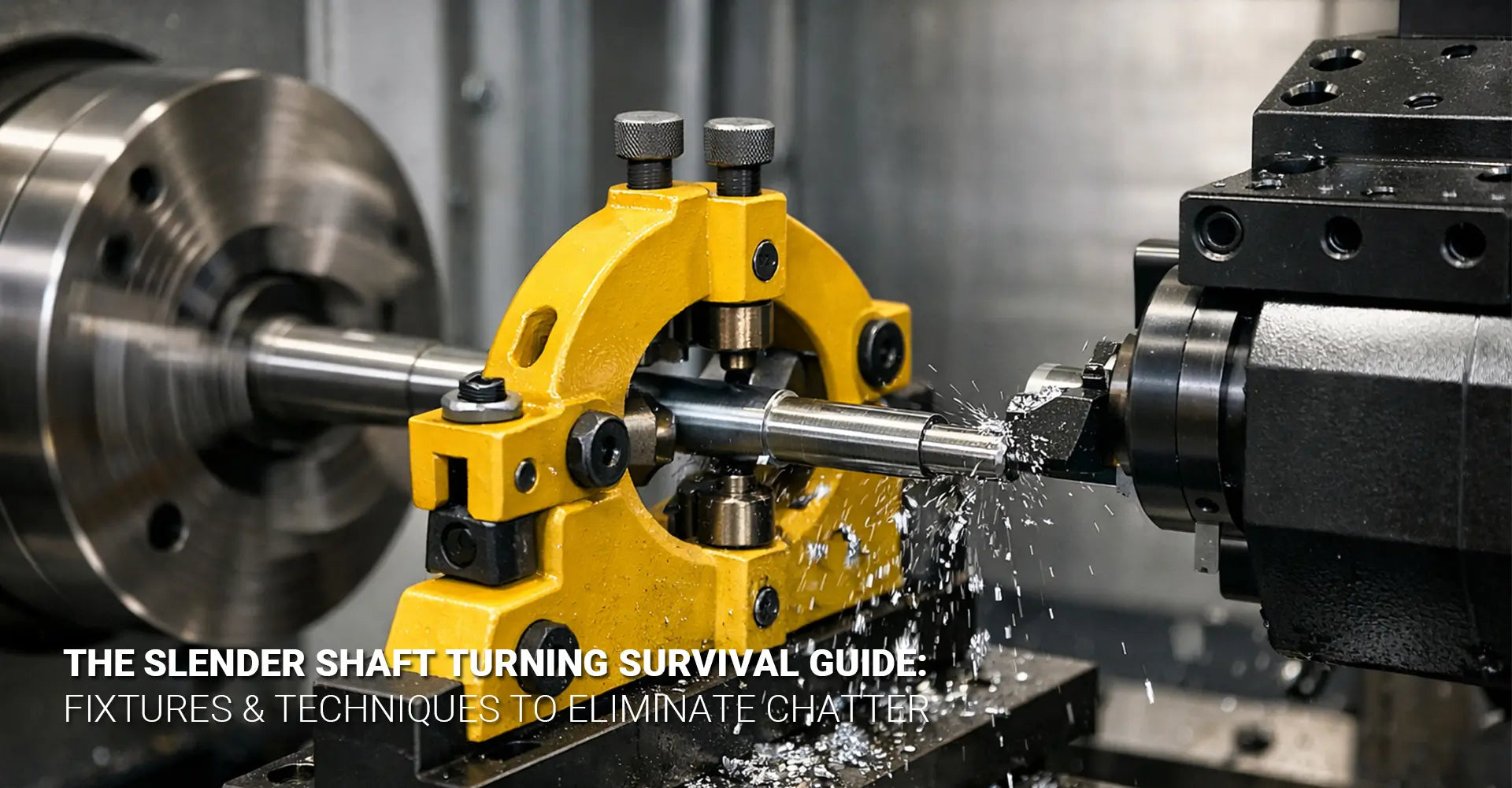
How Do You Stop Slender Shafts from Vibrating During CNC Turning?
How Do You Stop Slender Shafts from Vibrating During CNC Turning?

Machining slender shafts on a CNC lathe presents one of the most frustrating challenges in precision manufacturing. When you're working with long, thin components, vibration and deflection can turn a straightforward job into a nightmare of chatter marks, dimensional errors, and scrapped parts. Whether you're producing drive shafts for automotive applications or precision spindles for industrial machinery, understanding how to properly fixture and support these challenging workpieces is absolutely critical for success.
Quick Answer: What You Need to Know Right Now
The Fast Solution for Slender Shaft Turning:
Use a follow rest when you need moving support that travels with your cutting tool
Install steady rests at fixed points along the shaft to prevent sagging and bending
Keep cutting forces minimal by selecting sharp inserts with positive rake angles
Take light passes with multiple cuts instead of one heavy removal
Set up alignment perfectly before making your first cut to establish a clean reference surface
This approach reduces vibration by 70-80% compared to unsupported turning operations.
Understanding the Challenge
Before diving into solutions, let's address why this problem exists in the first place. Additionally, knowing the root cause helps you choose the right fixture strategy for your specific job. Therefore, we'll explore both the physics and the practical implications of working with extended workpieces.
Table of Contents
1. Why Do Slender Shafts Vibrate and Deflect During Turning?
2. What's the Difference Between Follow Rests and Steady Rests?
3. How Should You Set Up Your Fixture for Maximum Stability?
4. Which Cutting Parameters Prevent Chatter on Thin Shafts?
5. Conclusion
Why Do Slender Shafts Vibrate and Deflect During Turning?
Understanding the mechanics behind slender shaft turning vibration helps you prevent problems before they start. Moreover, this knowledge guides your decisions about which fixtures and techniques will work best for your specific application.
The Core Problem Explained
Here's what happens during unsupported slender shaft machining:
Length-to-diameter ratios exceeding 10:1 create cantilever beam conditions that amplify deflection
Cutting forces push the workpiece away from the tool, causing dimensional inaccuracy
Harmonic vibration builds up when the natural frequency of the shaft matches the cutting frequency
Heat generation further reduces stiffness and increases deflection during the cut
The Physics Behind the Problem
When you apply cutting force to a long, unsupported shaft, physics works against you. Specifically, the shaft acts like a spring that stores energy and releases it as vibration. Furthermore, as the length increases or diameter decreases, the moment of inertia drops dramatically, making the shaft exponentially more flexible.
The relationship follows the classic beam deflection formula, where deflection increases with the cube of the length but decreases with the fourth power of the diameter. Consequently, even small changes in these dimensions create massive differences in stability. For instance, doubling the length increases deflection by eight times, while halving the diameter increases it by sixteen times.
Material stiffness plays a crucial role too. Steel shafts behave differently than aluminum or titanium versions of the same geometry. Additionally, the unsupported length between the chuck and any rest determines the critical vibration frequency. When your spindle speed creates a cutting frequency that matches this natural frequency, you get severe chatter that ruins the surface finish and can even damage your tooling.
This is particularly challenging in CNC machining service operations where tight tolerances are required across various materials and geometries.
What's the Difference Between Follow Rests and Steady Rests?
Choosing between a follow rest steady rest setup requires understanding how each type supports your workpiece. Moreover, many jobs benefit from using both types simultaneously for maximum stability.
The Two Main Support Methods
Steady Rest Characteristics:
Bolts directly to the lathe bed at a fixed position
Supports the shaft at one stationary point along its length
Works best for preventing sag in the middle of long workpieces
Remains in place while the carriage and tool move past it
Follow Rest Characteristics:
Attaches to the carriage and travels with the cutting tool
Provides support immediately behind the cutting zone
Prevents the shaft from deflecting away from the tool during the cut
Moves along the entire length of the shaft as you machine

When to Use Each Type
Steady rests excel when you're dealing with extremely long shafts that sag under their own weight. Essentially, they act like a bearing that holds the center portion of the shaft in position. However, they don't move with your tool, so they can't directly counteract cutting forces at the point of contact.
Follow rests shine when you need to maintain tight tolerances along the entire length of a shaft. Because they travel with the carriage, they provide support exactly where cutting forces are applied. This makes them invaluable for thin diameter shaft machining where even slight deflection creates out-of-round conditions.
Many experienced machinists combine both approaches. First, they'll position a steady rest near the center of a very long shaft for general support. Then, they'll add a follow rest that moves with the tool for precision cuts. This combination handles both sag and cutting force deflection simultaneously.
In electronics manufacturing applications where component shafts might be just a few millimeters in diameter, the follow rest becomes absolutely essential for maintaining the required precision.
How Should You Set Up Your Fixture for Maximum Stability?
Proper CNC turning slender shaft fixture setup makes the difference between a successful job and a pile of scrap. Furthermore, the setup sequence matters just as much as the fixtures themselves.
Your Step-by-Step Setup Checklist
Critical Setup Steps in Order:
1. Support the free end first using a tailstock center or live center
2. Face the end clean to create a true perpendicular surface
3. Machine a reference diameter of at least 2-3 inches for your fixture to ride on
4. Position your steady rest or follow rest aligned with this reference section
5. Adjust contact points until they just barely touch with no visible gap
6. Apply cutting fluid or way oil to all contact surfaces to prevent galling
7. Test with a light pass before committing to full depth cuts

The Details That Make It Work
The single most important factor in CNC lathe fixture design is establishing that initial reference diameter. If you try to set up your rest against raw stock that's out-of-round or has mill scale, you'll never get consistent support. Instead, always machine a clean, concentric section first, even if it's just 0.010" off the diameter.
Contact point adjustment requires a delicate touch. Too loose, and the rest provides no support when cutting forces push the shaft. Too tight, and you create friction that heats the shaft and actually makes deflection worse. The sweet spot is when you can just barely feel resistance when rotating the shaft by hand, but it still turns freely.
Lubrication isn't optional. Dry contact between hardened fixture surfaces and your workpiece creates heat and can score the finished diameter. A steady drip of cutting fluid or a brush application of way oil keeps everything cool and prevents surface damage.
Many machinists make the mistake of setting up their fixture once and forgetting about it. However, as you remove material and the shaft diameter decreases, you need to readjust the contact points. Therefore, check and adjust your rest after every significant diameter change.
This careful setup approach is essential whether you're working on prototype parts or high-volume production runs for automotive suppliers.
Which Cutting Parameters Prevent Chatter on Thin Shafts?
Even with perfect fixturing, wrong cutting parameters will still cause chatter reduction long shafts to fail. Moreover, parameter selection works hand-in-hand with tool geometry for slender work to create stable cutting conditions.
Your Parameter Starting Points
Recommended Ranges for Slender Shaft Turning:
Cutting Speed: 250-400 SFM for steel, 600-800 SFM for aluminum (higher speeds reduce cutting force)
Feed Rate: 0.002-0.006 inches per revolution (lighter feeds minimize radial pressure)
Depth of Cut: 0.005-0.012 inches per pass (multiple light cuts beat one heavy cut every time)
Tool Nose Radius: 0.016" or smaller (reduces contact area and radial force)
Rake Angle: +5° to +15° positive (promotes shearing action with less force)
Note: These are starting points. Always begin conservatively and increase gradually based on results.
How Each Parameter Affects Stability
Cutting speed has a counterintuitive relationship with chatter. Higher speeds actually reduce cutting forces because they promote shearing rather than tearing of the material. Additionally, higher speeds move through the natural vibration frequency of the shaft more quickly, giving vibrations less time to build up. However, you must balance this against tool life and heat generation.
Feed rate directly controls how much material each cutting edge removes per revolution. Light feeds mean each tooth takes a smaller bite, which generates less radial force pushing the shaft away from the tool. Nevertheless, feeds that are too light can cause rubbing instead of cutting, which creates heat without removing material efficiently.
Depth of cut might be the most critical parameter for chatter prevention. Taking one 0.030" deep cut applies three times the radial force of a 0.010" cut. Therefore, it's almost always faster and more reliable to make three light passes than one heavy pass, even though it seems less productive. The time saved by avoiding chatter marks and rework far exceeds the extra spindle time.
Tool geometry deserves special attention when working with slender parts. A sharp insert with a large positive rake angle cuts like a knife through butter, requiring minimal force. In contrast, a worn or negative rake tool pushes material more than it cuts, creating huge deflecting forces. The nose radius also matters—a smaller radius concentrates force on a smaller area, which sounds bad but actually reduces the total radial pressure component.
Insert position matters too. Your tool must be set exactly on centerline height. Even 0.010" above center creates a lifting force component that amplifies vibration. Similarly, tool overhang should be minimized to prevent tool deflection from adding to workpiece deflection.
These principles apply across all CNC turning operations, but become absolutely critical when working with challenging geometries.
Conclusion
Successfully machining slender shafts requires three elements working together in harmony. First, you need proper mechanical support through carefully selected and positioned fixtures—whether that's a follow rest, steady rest, or combination of both. Second, you must optimize your cutting parameters to minimize the forces trying to push your workpiece away from the tool. Third, you need meticulous setup procedures that establish good reference surfaces and maintain proper alignment throughout the job.
The good news is that once you understand these principles, slender shaft work becomes predictable and repeatable. Start with conservative settings—lighter cuts, moderate speeds, and proper support. Then, gradually push the envelope based on the results you're seeing. Listen to your machine, watch for vibration, and adjust before problems develop.
Remember that every material, diameter, and length combination behaves slightly differently. What works perfectly for a 1-inch diameter steel shaft might need adjustment for a 0.5-inch aluminum version. Therefore, keep notes on what works for your specific applications, building a reference library of proven parameters.
Most importantly, don't skip the setup steps to save time. Those few extra minutes spent establishing a clean reference diameter and properly adjusting your fixtures will save hours of troubleshooting and rework later. Chatter prevention is always easier than chatter correction.
Whether you're working on components for industrial machinery or precision parts for other applications, mastering slender shaft turning opens up capabilities that set you apart from shops that shy away from these challenging jobs.
External Resources Worth Exploring
[CNC turning slender shaft fixture][^1]
[Chatter reduction long shafts][^2]
[Slender Shaft Machining][^3]
[CNC Lathe Stability][^4]
[Thin diameter shaft machining][^5]
[Follow Rest for CNC][^6]
---
[^1]: Explore this link to understand the design and functionality of CNC turning fixtures, crucial for precision machining.
[^2]: Learn about effective techniques for reducing chatter in machining, enhancing product quality and tool life.
[^3]: Explore this link to learn effective techniques and tips for machining slender shafts, enhancing precision and efficiency.
[^4]: Discover strategies to enhance CNC lathe stability, ensuring better performance and accuracy in your machining processes.
[^5]: Exploring this resource will provide you with essential techniques and insights to enhance your machining processes.
[^6]: This link will help you understand the benefits of using Follow Rest in CNC operations for better precision and efficiency.


“Great article on managing vibration in slender shaft machining! It got me thinking – how do performance marketing agencies like https://collaba.digital/performance-agency handle ‘vibration’ in their client campaigns? You mentioned harmonic frequencies causing issues in machining – do digital marketers face similar challenges with campaign resonance when scaling ad spend across platforms? The parallels between precision engineering and data-driven marketing are fascinating!”