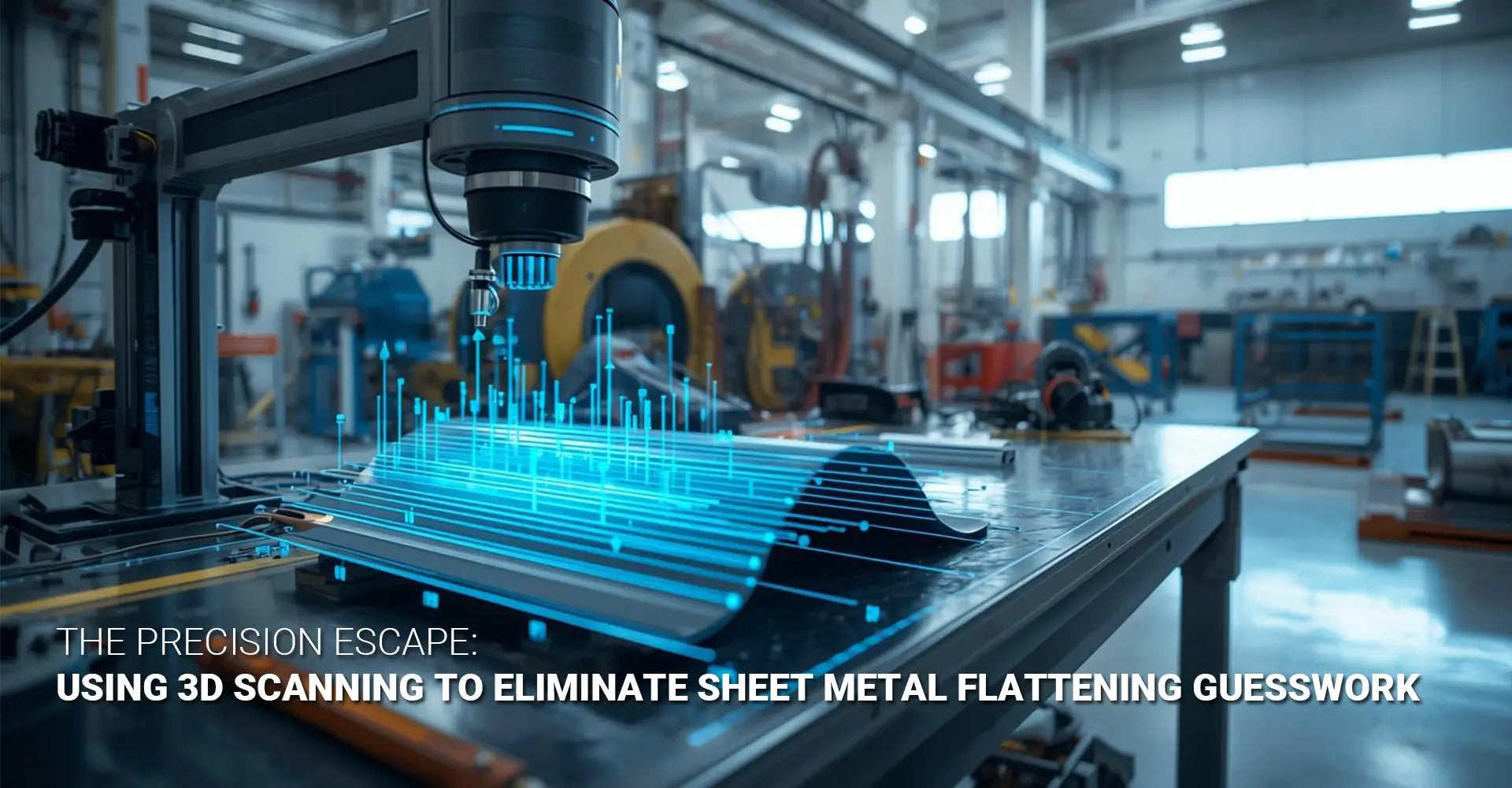
How Can 3D Scanning Fix Your Sheet Metal Flattening Errors?
How Can 3D Scanning Fix Your Sheet Metal Flattening Errors?

Every fabricator knows the frustration. You carefully calculate your flat pattern, set up the press brake, and make the bend—only to find the finished part doesn't match your specifications. The holes are misaligned. The flanges are too long or too short. Moreover, what worked perfectly yesterday fails today with a new material batch. Traditional K-factor charts promise accuracy, but they can't account for the real-world variables in your shop. Consequently, you're left with costly scrap, endless rework, and frustrated customers waiting for parts.
Quick Answer: What You Need to Know Right Now
Sheet metal flattening accuracy 3D scan technology captures your bent parts with ±0.025mm precision, letting you reverse-engineer the exact K-factor your machine produces. This eliminates guesswork, cuts scrap by up to 40%, and gets your flat patterns right the first time. Furthermore, this approach is especially critical for 5-axis CNC sheet metal fabrication where precision matters most. Instead of relying on generic charts, you measure what actually happens on your equipment with your materials, then use that data to create compensated blanks that bend perfectly every time.
Understanding why traditional methods fail is the first step toward better results. Therefore, let's examine the hidden variables that cause your bent parts to miss their targets, and then explore how digital measurement solves these age-old problems.
Table of Contents
- Why Do Your Bent Parts Never Match the Drawings?
- What Makes 3D Scanning Better Than Manual Measurement for Sheet Metal?
- How Do You Calculate Real K-Factors from 3D Scan Data?
- Why Does 5-Axis CNC Matter for Compensated Blank Development?
Why Do Your Bent Parts Never Match the Drawings?
The Reality Gap in Sheet Metal Fabrication
Standard K-factor charts give you a starting point, but they assume perfect conditions that rarely exist in real production environments. Your actual results depend on dozens of variables that change daily. As a result, even experienced operators struggle to predict how a new part will behave during bending.
The Core Problem Explained Simply
Here's what's really happening: Material properties vary between lots, even from the same supplier. Your press brake tooling wears gradually, changing the actual bend radius. Temperature affects springback behavior. Machine calibration drifts over time. Additionally, operator technique introduces subtle variations. These factors combine to create unpredictable results that no chart can anticipate.
Understanding the Variables That Charts Miss
Let's break down the specific issues. First, material hardness varies within specified ranges—a sheet stamped "304 stainless" might test anywhere from 70 to 85 on the Rockwell B scale. This difference significantly affects springback. Second, your punch and die condition matters enormously. A punch radius that started at 0.125" might measure 0.140" after thousands of bends, yet you're still using the original K-factor.
Third, grain direction influences bending behavior. Bending parallel to the grain produces different results than bending perpendicular to it. However, most fabricators don't track this consistently. Fourth, even slight variations in material thickness—within tolerance—change the neutral axis location and therefore the K-factor.
Finally, press brake setup parameters like back gauge position, ram speed, and dwell time all affect the final part geometry. Nevertheless, these parameters often change between operators or shifts without documentation. The cumulative effect creates a situation where consistency becomes nearly impossible using traditional methods alone.
What Makes 3D Scanning Better Than Manual Measurement for Sheet Metal?
Moving Beyond Calipers and Protractors
Manual measurement tools have served the industry for decades, but they introduce significant error when measuring bent parts. A caliper might tell you a flange length, yet it can't capture the true three-dimensional geometry. Similarly, a protractor gives you an angle reading, but reading errors and surface irregularities compromise accuracy.
The Accuracy Revolution in Numbers
Digital capture changes everything. Traditional manual measurement typically achieves ±0.5mm accuracy at best, and that's with skilled operators taking multiple readings. In contrast, professional-grade 3D scanners capture entire part geometries with ±0.025mm to ±0.1mm accuracy. That's an order of magnitude improvement. Moreover, the scanner captures thousands of data points in minutes, whereas manual measurement of a complex part might take hours.

The Complete Digital Measurement Workflow
Setting up for accurate scanning requires some attention to detail, but the process is straightforward. First, choose the right scanner for your part size and required accuracy. Structured light scanners work well for most sheet metal fabrication applications, offering excellent accuracy at reasonable cost. Laser scanners provide higher precision for critical components.
Next, prepare your part by cleaning it and applying target markers if needed. These targets help the scanner software align multiple scans into a complete model. Then, position the part to allow access to all surfaces. You'll typically need 3-5 scan positions for a simple bracket, more for complex assemblies.
During scanning, maintain consistent lighting and avoid vibration. The scanner projects patterns onto the part and captures how they distort, calculating surface geometry from this data. After scanning, the software stitches together multiple views into a unified point cloud—essentially a three-dimensional map of your part's actual surface.
This point cloud contains millions of measurements, capturing every detail of your bent part's geometry. Subsequently, you'll use this data to extract the precise dimensions needed for reverse engineering bend allowance calculations. The entire process typically takes 15-30 minutes per part, yet it provides data quality that manual measurement simply cannot match.
How Do You Calculate Real K-Factors from 3D Scan Data?
From Point Cloud to Actionable Parameters
Once you have your scan data, the real value comes from converting those millions of points into meaningful fabrication parameters. This process, called reverse engineering, extracts the exact dimensions and angles from your actual bent part. Then, you compare these measurements to your original flat pattern to determine what really happened during bending.
Step-by-Step: Extracting Your True K-Factor
Here's the calculation workflow: First, import your point cloud into CAD software that supports scan-to-CAD operations. Popular choices include Geomagic Design X, PolyWorks, or even advanced features in SolidWorks and Fusion 360. These programs let you fit precise geometric features—planes, cylinders, lines—to your scan data.
Start by identifying the flat sections of your bent part. Fit planes to these areas, which represent the flanges. Next, identify the bend zones and fit cylinders or conic sections to these regions to determine the actual bend radius. Then, measure the angles between your fitted planes—these are your true bend angles, accounting for springback.
The Math That Reveals Machine Reality
Now comes the critical calculation using 3D scanning for K-factor calculation. Measure the distance along the outside surface of your bent part from one end to the other, following the contour. This is your developed length—what the material actually stretched to during bending. Additionally, measure the inside radius that your scanner captured.
Compare this to what your flat pattern predicted. The difference reveals your actual K-factor. Specifically, use this formula: K = (developed length - outside setback - outside setback) / (π × angle × (inside radius + material thickness)). This sounds complex, but modern software automates the calculation once you identify the key features.
What you're discovering is your effective K-factor—the real parameter that produces accurate parts on your specific equipment with your specific materials. Furthermore, this laser scan to CAD for bending approach gives you data you can trust because it comes from actual measurements, not assumptions. Some shops find their real K-factor differs from chart values by 15-20%, which explains why their parts never matched predictions.
For parts with multiple bends, repeat this process for each bend zone. You might discover that your press brake produces slightly different K-factors at different positions along the bed, or that different bend angles require different parameters. This level of detail transforms your fabrication from art to science.
Why Does 5-Axis CNC Matter for Compensated Blank Development?
Precision Input Requires Precision Output
You've done the hard work of measuring your parts and calculating accurate parameters. Now you need to act on that data by creating compensated blank development that accounts for your actual bending behavior. This is where cutting technology makes a significant difference. A standard laser cutter or punch press can cut your corrected outline, but a 5-axis CNC machining service takes precision to another level.
The Multi-Axis Advantage Explained
Here's why five axes matter: Traditional 2D cutting creates your flat pattern outline accurately, yet it cannot guarantee feature positioning relative to bend lines after forming. When material stretches or compresses during bending, holes and slots can shift slightly from their intended positions. Additionally, if your part has features on multiple planes or requires precision edge preparation, 2D cutting falls short.

The Complete Compensated Blank Workflow
A 5-axis CNC machine can perform first-article inspection sheet metal operations right on the blank before bending. It creates not just the corrected outline, but also precision-drills pilot holes, mills slots, chamfers edges, and even creates partial bends or relief cuts—all with perfect positional accuracy relative to your calculated bend lines. This capability is particularly valuable for automotive and industrial machinery applications where tolerances are tight.
The workflow starts with your corrected flat pattern CAD file. Your CAM software programs tool paths that account for material thickness, creating features in the exact positions that will align correctly after bending. Then, the 5-axis machine executes these paths with repeatability measured in microns.
For example, consider a bracket with mounting holes that must align within ±0.1mm after bending. A laser cutter might place those holes accurately on the flat blank, but material flow during bending can shift them. However, when you've used scan data to predict exactly how material flows, and then use 5-axis CNC to place features in pre-compensated positions, your bent part achieves target accuracy.
This approach also supports creating a digital twin for press brake operations. By scanning completed parts and comparing them to your digital model, you create a feedback loop. Therefore, you can track how your process drifts over time and make corrections before producing scrap. Some advanced shops even use this data to automatically adjust their flat pattern calculations, creating a self-correcting system.
The investment in 5-axis capability pays off quickly when you consider scrap reduction. If you're currently scrapping 10-15% of complex parts due to feature misalignment, and each part costs $50-200 in material and labor, eliminating that scrap through precise compensated blanks recovers your investment rapidly. Moreover, you can confidently quote tighter tolerances, opening new market opportunities.
For shops also offering 3D printing services, this digital workflow integrates naturally. You might prototype a design in plastic, scan it for validation, then use that same scan data to create perfect sheet metal production versions. The entire digital thread—from concept through production—maintains consistency and accuracy.
Conclusion
Sheet metal fabrication has relied on experience and iteration for too long. However, 3D scanning technology brings precision measurement to a craft that deserves better tools. By capturing actual part geometry with sub-millimeter accuracy, you eliminate the guesswork that creates scrap and delays.
The workflow is clear: scan your bent parts, reverse-engineer the actual parameters your equipment produces, calculate compensated flat patterns, and machine those blanks with 5-axis precision. Each step builds on digital data rather than assumptions. As a result, your first bent part matches specifications, your production runs maintain consistency, and your customers receive quality that builds trust.
The initial time investment pays dividends immediately. Instead of multiple trial-and-error cycles consuming days and materials, you achieve accuracy on the second attempt—the first compensated blank. For high-volume work, even tiny improvements in K-factor accuracy multiply across thousands of parts, eliminating waste. For complex, low-volume projects, the cost of one failed first article often exceeds the entire scanning and analysis expense.
Moving forward, consider this approach for any critical sheet metal component. Start with your most problematic parts—the ones that currently require multiple iterations or consistently fall outside tolerance. Scan them, calculate real parameters, and prove the process on known challenges. Then, expand the methodology across your product line.
The shops winning tomorrow's contracts will be those that combine traditional craftsmanship with digital precision. This technology doesn't replace skilled fabricators; rather, it gives them tools that match their expertise. When you know exactly what your equipment does, you control outcomes instead of hoping for them.
External Links & Resources
[sheet metal flattening accuracy 3D scan][^1]
[Reverse engineering bend allowance][^2]
[3D scanning for K-factor calculation][^3]
[Compensated blank development][^4]
[5-axis CNC sheet metal fabrication][^5]
[Laser scan to CAD for bending][^6]
-----
[^1]: Understanding this concept is crucial for achieving precise metal fabrication and improving product quality.
[^2]: Exploring this topic can enhance your knowledge of metalworking processes and improve design accuracy.
[^3]: Explore this link to understand how 3D scanning can enhance accuracy in K-factor calculations, crucial for manufacturing and design.
[^4]: Discover the significance of compensated blank development in optimizing production processes and improving product quality.
[^5]: Exploring this link will provide insights into the advantages and applications of 5-axis CNC technology in sheet metal fabrication.
[^6]: This resource will help you understand the process and benefits of converting laser scans into CAD models for precise bending.


