How Can You Slash CNC Machining Costs Through Smarter Design Choices?
How Can You Slash CNC Machining Costs Through Smarter Design Choices?

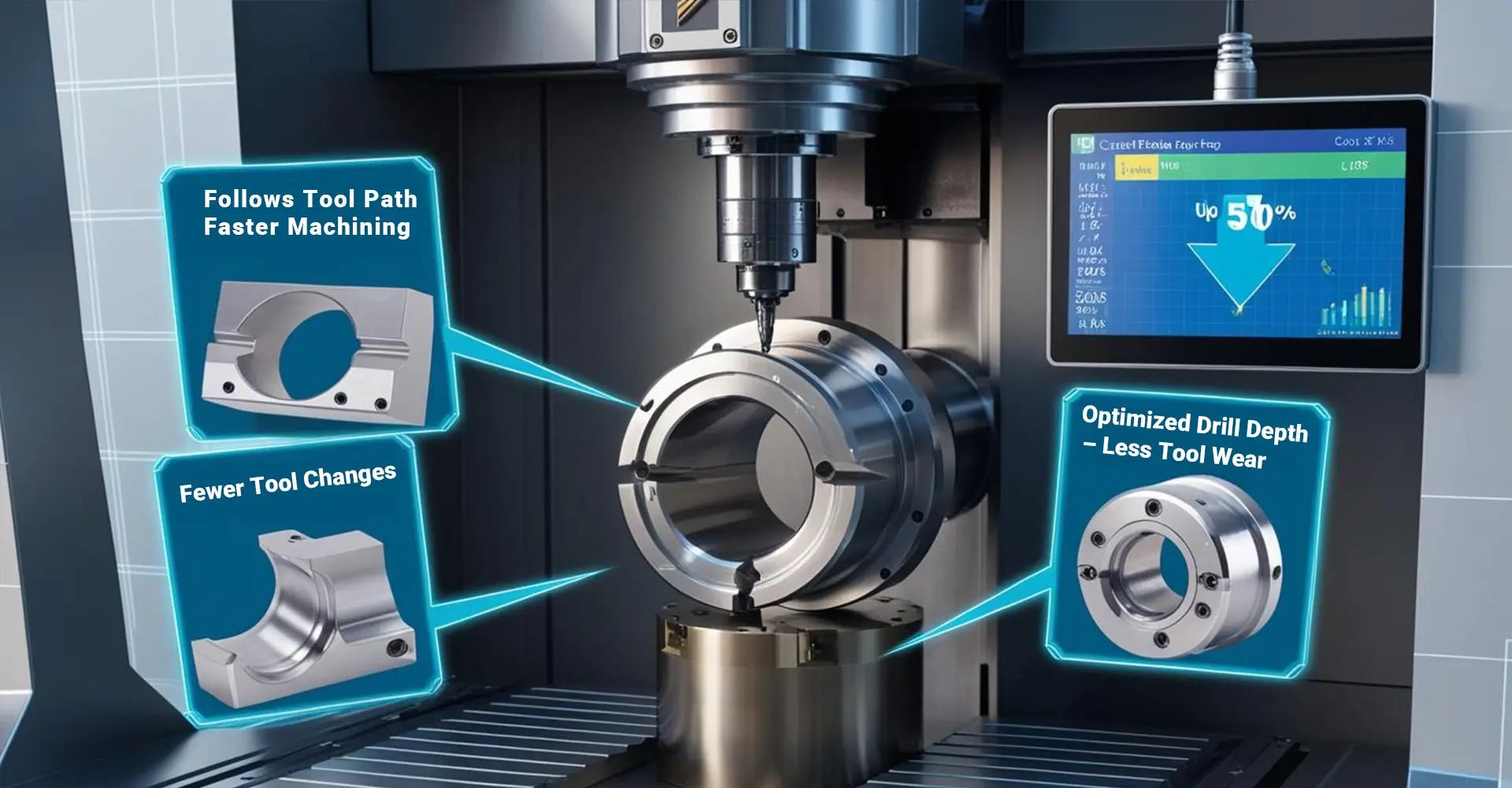
In today's competitive manufacturing landscape, every dollar counts. What many engineers and product designers don't realize is that up to 80% of your CNC machining costs are determined before the first cut is ever made. The design decisions you make at your desk can have dramatic financial implications on the shop floor. Understanding and implementing CNC machining cost reduction design tips isn't just about saving money—it's about creating more efficient, manufacturable products.
By focusing on three critical design principles—limiting hole depth, standardizing thread specifications, and strategically applying tolerances—you can potentially reduce your CNC machining costs by up to 50%. These low-cost CNC part design strategies don't require advanced software or expensive consultants; they simply leverage smart design practices that work with the machining process rather than against it.
Design for manufacturability (DFM) for CNC isn't a new concept, but it remains surprisingly underutilized. Many designers continue to create parts that look perfect in CAD but cause unnecessary complications, extended machining times, and inflated costs during production. By understanding the relationship between design choices and manufacturing processes, you can create parts that maintain functionality while being significantly more economical to produce.
Table of Contents
- Why Do Simple Design Changes Lead to Dramatic Cost Savings in CNC Machining?
- How Does Hole Depth Affect Your CNC Machining Budget?
- Why Should You Standardize Thread Specifications in Your CNC Projects?
- When Should You Apply Different Tolerance Levels in Your Design?
- What Real Results Can These Design Principles Achieve?
- Conclusion
Why Do Simple Design Changes Lead to Dramatic Cost Savings in CNC Machining?
The complexity of your design directly impacts machining time, tool wear, setup requirements, and ultimately, your bottom line. Every feature you add—each hole, pocket, or contour—requires additional operations, potentially different tools, and more machine time. Understanding the major cnc machining cost factors allows you to make informed decisions that preserve part functionality while drastically reducing manufacturing expenses.
Consider this: A seemingly minor design modification like changing an internal corner from sharp to rounded can reduce machining time by up to 30%. Why? Because CNC mills use round cutting tools that naturally create rounded internal corners. Forcing the machine to create sharp corners requires additional passes and specialized techniques that drive up costs unnecessarily.

When analyzing cost-driving design elements, three factors consistently emerge as the most impactful: deep holes that exceed standard cutting depth ratios, non-standardized threading that requires frequent tool changes, and unnecessarily tight tolerances across non-critical features. By addressing these specific elements, manufacturers working with various metals and plastics can achieve remarkable cost reductions without compromising part integrity. The compounding effect of multiple design optimizations can transform an expensive, hard-to-manufacture part into an economical production-friendly component.
How Does Hole Depth Affect Your CNC Machining Budget?
Deep holes represent one of the most challenging operations in CNC machining. As drill depth increases, problems multiply: chips become difficult to evacuate, cutting tools deflect more easily, and the risk of tool breakage rises dramatically. Avoiding deep holes in CNC design isn't just good practice—it's essential for controlling costs and ensuring manufacturing consistency.
Industry data shows that limiting hole depths to a maximum of 6 times the hole diameter (6xD) can reduce drilling cycle time by up to 40% compared to deeper holes. In one documented case study, reducing hole depths from 8xD to 5xD decreased tool breakage rates by 40% and cut overall processing time by nearly one-third.
When designing holes for your CNC machined parts, consider the physics involved. Each millimeter beyond the 6xD threshold exponentially increases machining difficulty. Deep holes require slower spindle speeds, more frequent pecking cycles (where the drill repeatedly retracts to clear chips), and special tooling—all of which add cost. If your design absolutely requires deeper holes, consider alternative manufacturing methods like gun drilling or EDM for those specific features while keeping the rest of the part CNC-machinable. Remember that every design decision ripples through the entire manufacturing process, affecting everything from tool life to surface finish quality.
Why Should You Standardize Thread Specifications in Your CNC Projects?
Every different thread specification in your design requires a separate threading tool and a new setup operation. While this might seem inconsequential in CAD, on the shop floor it translates to machine downtime, additional tool costs, and increased opportunity for errors. Implementing standardized thread specifications for machining across your designs can dramatically streamline production.
The numbers speak for themselves: mixed thread specifications typically add approximately 15 minutes of setup time per tool change, whereas standardized threading (like using M6 threads throughout) can reduce this to just 5 minutes per setup. This 10-minute difference might seem small, but multiplied across multiple thread types and production runs, it quickly adds up to significant cost savings of up to 30%.
Beyond setup time, thread standardization offers several additional benefits. It reduces inventory requirements for both tooling and fasteners, simplifies assembly procedures, and minimizes the risk of cross-threading during product assembly. When designing components for industrial machinery, consider standardizing on M6 threads wherever possible, using alternatives only when absolutely necessary due to space or load-bearing requirements. Even in cases where mixed threads are unavoidable, try to minimize variations—for example, using M6 for 80% of fasteners and M4 only where space constraints exist, rather than incorporating five or six different thread specifications.
When Should You Apply Different Tolerance Levels in Your Design?
Not all features on your part require the same precision. Applying tight tolerances universally across a design is one of the most common and costly mistakes in CNC part development. Tolerance optimization for cost-effective CNC involves strategically identifying which dimensions are truly critical to functionality and which can be manufactured to more relaxed standards.
Data from production environments shows that machining a surface to ±0.05mm tolerance might take twice as long as machining the same surface to ±0.1mm. By implementing tiered tolerance specifications—using tighter tolerances only where functionally necessary—manufacturers have documented time savings of 25% on typical components, with corresponding cost reductions.

Understanding tolerance in cnc machining requires recognizing the relationship between precision and cost. Critical dimensions—like mating surfaces, bearing seats, or precision locating features—often genuinely need tight tolerances of ±0.05mm or better. However, non-critical features such as overall length, decorative elements, or mounting brackets can frequently use more relaxed tolerances like ±0.1mm with zero impact on functionality. Many designers are surprised to learn that following ISO 2768 tolerance guidelines for CNC can provide an excellent framework for appropriate tolerance allocation, helping achieve 50% cost reduction in CNC part design through this strategy alone. The cost savings come not just from reduced machining time but also from lower inspection requirements and decreased scrap rates.
What Real Results Can These Design Principles Achieve?
Theory is valuable, but real-world results prove the case. Consider a recent project involving industrial sensor housings that were originally expensive to produce. By applying the three design principles discussed—hole depth limitation, thread standardization, and strategic tolerance allocation—the manufacturer achieved remarkable cost improvements while maintaining all functional requirements.
The industrial sensor housing case study demonstrated the power of design optimization: The original cost of $18.50 per unit plummeted to just $8.70 after redesign—a 53% reduction. Most importantly, this dramatic saving came without changing the material, the primary dimensions, or compromising any performance characteristics.
Breaking down the sensor housing redesign reveals how each principle contributed to the overall savings. First, redesigning four deep holes (previously 7xD) to stay within the 6xD guideline reduced machining time by 18%. Next, standardizing all threads to M6 eliminated two tool changes and simplified programming, contributing another 12% cost reduction. Finally, applying tiered tolerances—maintaining ±0.05mm only on critical sealing surfaces and sensor mounting points while relaxing other tolerances to ±0.1mm—delivered the remaining 23% savings. The surface finish requirements remained unchanged, preserving the product's appearance and functional properties while dramatically improving its cost structure.
Conclusion
Smart design choices can have a profound impact on CNC machining costs. By implementing the three key principles we've explored—limiting hole depth to 6xD, standardizing thread specifications, and strategically applying tolerances—you can potentially reduce your manufacturing expenses by up to 50%.
These approaches don't require revolutionary changes to your design process. Rather, they involve making informed decisions that align with manufacturing realities. Remember that the most elegant engineering solution isn't just about performance—it's about achieving that performance in the most economical way possible.
As you develop your next component for CNC machining, take time to review these principles. Your manufacturing partners will thank you, and so will your budget.
Additional Resources
[CNC machining cost reduction][^1]
[Design for manufacturability (DFM) for CNC][^2]
[Low-cost CNC part design strategies][^3]
[50% cost reduction in CNC part design][^4]
[ISO 2768 tolerance guidelines for CNC][^5]
[tolerance in cnc machining][^6]
[cnc machining cost factors][^7]
---
[^1]: Discover effective strategies for reducing CNC machining costs, which can lead to increased profitability and competitiveness in your projects.
[^2]: Understanding DFM can significantly enhance your CNC machining efficiency and cost-effectiveness. Explore this resource to learn more.
[^3]: Implementing low-cost design strategies can optimize your production process and save money. Check out this link for valuable insights.
[^4]: This link will guide you through innovative techniques and methods to significantly cut costs in CNC part design without compromising quality.
[^5]: Understanding ISO 2768 tolerance guidelines is crucial for ensuring precision in CNC machining. Explore this link to enhance your knowledge.
[^6]: Tolerance in CNC machining affects the quality and functionality of parts. Discover more about its significance and applications.
[^7]: Knowing the cost factors in CNC machining can help you budget effectively and optimize production. Learn more about these factors here.


