How Does TCPC Eliminate Manual Offsets in 5-Axis CNC Machining?
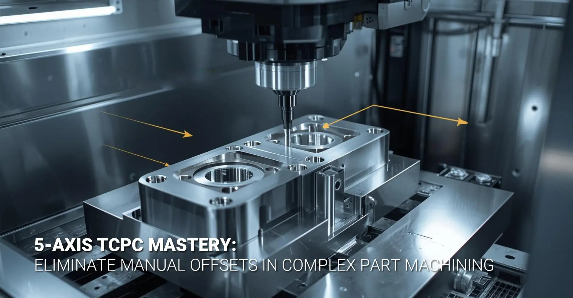
How Does TCPC Eliminate Manual Offsets in 5-Axis CNC Machining?

Picture this: You're programming a complex part with multiple angled features. Every time the rotary axes move, you're stuck calculating offsets manually. One small mistake means scrapped parts and wasted hours. This frustration is exactly what thousands of CNC programmers face daily when working without proper tool control systems. Fortunately, there's a proven solution that eliminates these headaches entirely.
Quick Answer: What You Need to Know Right Now
TCPC (Tool Center Point Control) automatically calculates rotary axis offsets, keeping your tool tip exactly where you programmed it. Instead of manually figuring out complex angle compensations, the CNC control handles all kinematic calculations in real-time. This means faster programming, fewer errors, and consistent results across complicated 5-axis operations.
Key Benefits at a Glance:
- Zero manual offset calculations – The control does all the math
- Faster programming time – Reduce setup from hours to minutes
- Higher accuracy – Eliminate human calculation errors
- Consistent results – Same precision across all rotary positions
- Simplified code – Program tool tip paths, not machine movements
Understanding TCPC and Your Workflow
Now that you know the basics, let's dive into how TCPC transforms your daily programming challenges. Whether you're machining aerospace components or automotive parts, understanding this technology will dramatically improve your results. The following sections break down everything from common problems to practical implementation steps.
Table of Contents
- Why Do Manual Offsets Create Programming Headaches?
- What Exactly Happens When You Activate TCPC Mode?
- How Do You Set Up TCPC in Mastercam Step-by-Step?
- Can You Share Working G-Code Examples for TCPC?
- Conclusion
Why Do Manual Offsets Create Programming Headaches?
The Hidden Costs of Traditional Programming
If you've ever programmed a 5-axis machine without TCPC, you already know the pain. Traditional methods require you to calculate every single offset manually whenever rotary axes move. This process consumes valuable time that could be spent on productive machining.
The Core Problems You're Fighting
Manual offset programming creates three major bottlenecks:
- Time consumption – Complex parts can take 3-5 times longer to program
- Error multiplication – Each calculation introduces potential mistakes
- Limited complexity – Programmers avoid difficult angles to reduce workload
These issues directly impact your bottom line. Additionally, training new programmers becomes harder because they must master complex geometric calculations before producing reliable code.
Real-World Impact on Production
Let's examine a typical scenario. Suppose you're machining a turbine blade with compound angles. Without TCPC, you'll spend hours calculating tool tip positions for each rotary move. Furthermore, if the part design changes, you're back to square one recalculating everything.
The math gets especially tricky when working with 5-axis dynamic offset requirements. Each axis movement affects the tool tip position in three-dimensional space. Consequently, programmers often simplify their approach, avoiding certain angles entirely. This limitation restricts design possibilities and forces compromises in part geometry.
Moreover, manual calculations become nearly impossible for simultaneous 5-axis contouring. When multiple axes move together, the geometric relationships change continuously. Therefore, most shops stick to simpler 3+2 positioning strategies, leaving performance on the table.
What Exactly Happens When You Activate TCPC Mode?
Breaking Down the Technology
When you enable TCPC, your CNC control transforms how it interprets programmed coordinates. Instead of treating each axis independently, the system understands the complete kinematic chain. This means it knows exactly how rotary movements affect tool tip position.
The Magic Behind the Scenes
TCPC maintains perfect tool tip positioning through three key functions:
- Real-time calculation – Control computes offsets 1000+ times per second
- Kinematic awareness – System understands your machine's physical structure
- Automatic compensation – Linear axes adjust to counteract rotary movement
Think of it like a skilled operator constantly adjusting all axes to keep the tool exactly on target. However, the control performs these adjustments faster and more accurately than any human could.
Understanding Tool Center Point Control 5-axis
The term "Tool Center Point Control 5-axis" describes how the system maintains the cutting edge at the programmed position. When you activate TCPC with G43.4, the control switches modes. Subsequently, all coordinate commands reference the tool tip rather than machine zero.
Here's what happens during a typical rotary move with TCPC active. First, you program a simple A-axis rotation of 45 degrees. Meanwhile, the control calculates how this rotation moves the tool tip away from the programmed position. Then, it automatically adjusts X, Y, and Z axes to compensate. As a result, your tool tip stays exactly where you programmed it.
Different control manufacturers use various names for this function. For instance, Fanuc calls it TCPC, Siemens uses TRAFOOF, and Heidenhain refers to it as M128. Nevertheless, they all accomplish the same goal through similar methods.
The control needs three critical pieces of information to work correctly. First, accurate tool length data tells the system how far the cutting edge extends. Second, precise work offset values establish the part's location. Third, correct kinematic parameters define your machine's physical structure. Without these elements, TCPC cannot calculate proper compensations.
How Do You Set Up TCPC in Mastercam Step-by-Step?
Preparing Your CAM Environment
Before diving into programming, proper configuration ensures success. Mastercam offers powerful TCPC capabilities, but only when set up correctly. Therefore, let's walk through each critical setting you need to verify.
Essential Configuration Checklist
Complete these steps before generating your first TCPC toolpath:
- Verify machine definition matches your physical equipment
- Configure post-processor for TCPC output
- Set up accurate tool library with precise length measurements
- Establish correct work coordinate system
- Enable 5-axis control parameters
Start by opening your machine definition file. Then, confirm that the kinematic structure matches your actual machine configuration. This step prevents countless headaches later because incorrect kinematics produce wrong code.
Complete Mastercam TCPC Tutorial
Following this Mastercam TCPC tutorial will save you hours of troubleshooting. First, launch Mastercam and load your part file. Next, select the Machine tab and choose your 5-axis machine definition. The software should display your machine's kinematic structure visually.
Now, navigate to the post-processor settings. Look for the TCPC or RTCP option and enable it. Some post-processors call this "Tool Center Point Control" while others use "Rotation Tool Center Point." Both terms refer to the same function.
After enabling TCPC, configure your tool data carefully. Each tool needs accurate length values measured from the spindle gauge line. Additionally, input the correct diameter and corner radius information. The control uses these values for compensation calculations, so precision matters here.
Next, establish your work coordinate system properly. Position your work offset at a logical location on the part. Many programmers place it at the center of rotation to simplify visualization. However, choose whatever makes sense for your specific application.
When creating toolpaths, select the appropriate 5-axis strategy. Mastercam offers several options including swarf milling, multi-axis contour, and flow line machining. For TCPC applications, these strategies automatically output code that references the tool tip position.
Before posting, verify your collision control settings. The software can check for interferences between the tool holder, machine components, and part geometry. This verification step becomes especially important when working with complex industrial machinery components.
Finally, post-process your toolpath and examine the output code. Look for the G43.4 command near the beginning of your program. This line activates TCPC mode. Also, verify that coordinate values make sense relative to your part geometry.
Can You Share Working G-Code Examples for TCPC?
Your First TCPC Program
Let's examine practical code you can test immediately. These examples demonstrate proper TCPC syntax for different scenarios. Moreover, they include common variations across popular control systems.
Basic TCPC Activation Code
Here's a simple example showing proper G-code for TCPC activation:
O1001 (TCPC TEST PROGRAM)
G90 G54 G00 X0 Y0 Z100.0
M06 T01 (10MM BALL ENDMILL)
S3000 M03
G43.4 H01 (ACTIVATE TCPC MODE)
G01 Z10.0 F1000
X50.0 Y30.0 Z5.0 F2000
A45.0 C30.0 (ROTARY MOVE WITH AUTOMATIC COMPENSATION)
G01 X75.0 Y45.0 (TOOL TIP STAYS ON PROGRAMMED PATH)
A0.0 C0.0 (RETURN TO NEUTRAL POSITION)
G00 Z100.0
G49 (CANCEL TCPC MODE)
M05
M30
This code demonstrates the essential G-code for TCPC structure. Notice how G43.4 activates the function, while G49 cancels it later. Between these commands, the control maintains tool tip position automatically.
Practical 5-Axis Machining Programming
Now let's explore more complex 5-axis machining programming scenarios. When machining precision CNC parts that require simultaneous axis movement, TCPC becomes absolutely necessary.
Here's an example for simultaneous 5-axis contouring:
O1002 (SIMULTANEOUS 5-AXIS WITH TCPC)
G90 G54 G00 X0 Y0 Z100.0
M06 T02 (6MM BALL ENDMILL)
S4000 M03
G43.4 H02 (TCPC ACTIVE)
G01 X25.0 Y25.0 Z10.0 A15.0 C0.0 F1500
X30.0 Y28.0 Z8.5 A18.0 C5.0 (ALL AXES MOVE TOGETHER)
X35.0 Y32.0 Z7.0 A22.0 C12.0
X40.0 Y35.0 Z6.0 A25.0 C18.0
(TOOL TIP FOLLOWS PROGRAMMED PATH EXACTLY)
G00 Z100.0
G49
M05
M30
During this program, all five axes move simultaneously. Meanwhile, TCPC ensures the tool tip traces your programmed path perfectly. Without TCPC, generating this code manually would be nearly impossible.
Understanding CNC Rotary Axis Compensation
The concept of CNC rotary axis compensation becomes clearer when you examine what happens without TCPC. Consider this comparison showing the same move with and without compensation:
Without TCPC (Manual Calculation Required):
G01 X50.0 Y30.0 Z5.0
A45.0
(PROGRAMMER MUST CALCULATE OFFSETS)
X52.147 Y32.147 Z3.536 (MANUALLY CALCULATED COMPENSATION)
With TCPC (Automatic Compensation):
G43.4 H01
G01 X50.0 Y30.0 Z5.0
A45.0 (CONTROL HANDLES COMPENSATION AUTOMATICALLY)
The difference in programming complexity becomes obvious immediately. Furthermore, the TCPC version eliminates calculation errors completely.
Advanced Implementation for Different Materials
When working with various materials like those in CNC metals and plastics, TCPC maintains consistent performance. Here's an example incorporating tool changes:
O1003 (MULTI-TOOL TCPC PROGRAM)
G90 G54 G00 X0 Y0 Z100.0
(FIRST TOOL - ROUGHING)
M06 T01
S2500 M03
G43.4 H01
G01 X30.0 Y30.0 Z5.0 F800
A30.0 C0.0
(ROUGHING MOVES...)
G49
(SECOND TOOL - FINISHING)
M06 T02
S4000 M03
G43.4 H02 (REACTIVATE TCPC WITH NEW TOOL)
G01 X30.0 Y30.0 Z5.0 F1200
A30.0 C0.0
(FINISHING MOVES...)
G49
M05
M30
Notice how TCPC gets cancelled and reactivated for each tool. This practice ensures the control uses correct length data for compensation calculations.
Control-Specific Variations
Different CNC controls implement 5 axis TCPC programming with slight syntax variations. Here are common alternatives:
Fanuc Style:
G43.4 H01 (TCPC ON)
G49 (TCPC OFF)
Siemens Style:
TRAFOOF (TCPC ON)
TRAORI (TCPC OFF)
Heidenhain Style:
M128 (TCPC ON)
M129 (TCPC OFF)
Check your machine's programming manual to confirm the correct syntax. However, the underlying principle remains identical across all systems.
Conclusion
TCPC technology transforms complex 5-axis programming from a mathematical nightmare into straightforward tool tip programming. By letting the control handle kinematic calculations automatically, you eliminate hours of manual work and countless opportunities for errors. This technology has become standard practice in modern CNC shops for good reason.
Starting with TCPC doesn't require jumping into complex parts immediately. Instead, begin with simple test programs to verify your machine configuration. Then, gradually increase complexity as you build confidence. Remember that accurate tool data and proper work offsets are absolutely critical for success.
The investment in learning TCPC pays dividends immediately through reduced programming time and improved accuracy. Moreover, it opens possibilities for machining complex geometries that would be impractical with manual offset calculations. Whether you're producing automotive components or other precision parts, TCPC gives you a significant competitive advantage.
Take the code examples from this article and test them on your machine today. Start simple, verify your results, and build from there. Your future self will thank you for making the switch to automated tool center point control.
Recommended Resources
[5 axis TCPC programming][^1]
[Tool Center Point Control 5-axis][^2]
[Mastercam TCPC tutorial][^3]
[CNC rotary axis compensation][^4]
---
[^1]: Understanding 5 axis TCPC programming can enhance your machining precision and efficiency. Explore this link for in-depth insights.
[^2]: Discover the mechanics of Tool Center Point Control in 5-axis machining to improve your technical knowledge and skills.
[^3]: The Mastercam TCPC tutorial offers valuable insights into toolpath compensation, essential for optimizing CNC operations. Check it out!
[^4]: Understanding CNC rotary axis compensation is crucial for precision machining. Explore this link to enhance your knowledge and skills.


