What Causes 5-Axis Singularity Issues and How Do They Ruin Surface Finish?
What Causes 5-Axis Singularity Issues and How Do They Ruin Surface Finish?

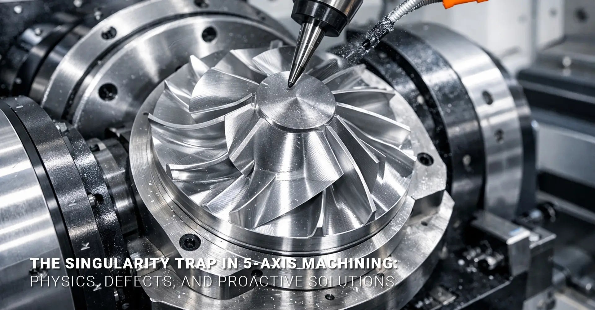
You've programmed the perfect toolpath. Your CNC machining service is running smoothly. Then suddenly, the rotary axes jerk violently, and your pristine part now has an ugly defect right in the middle of a critical surface. What just happened? You've just experienced a singularity—a mathematical trap that turns precision machining into a quality nightmare.
This article breaks down the physics behind 5 axis singularity issues, shows you exactly what they look like on your parts, and gives you practical strategies to prevent them before they happen.
Quick Answer: What You Need to Know Right Now
Key Takeaways:
- What it is: A singularity happens when rotary axes align, causing infinite speed calculations that the machine controller cannot solve
- What you see: Visible dimples, dwell marks, or gouges on finished parts where the tool passed through the singular point
- Main cause: Tool axis vectors passing through the rotational centerline (typically at A=90° or -90° on table-table machines)
- Primary fix: Tool axis tilt control in CAM programming to keep vectors away from dangerous alignments
- Backup solution: Post-processor kinematic filtering that automatically corrects unavoidable singular conditions
Understanding singularities isn't just theoretical knowledge. Therefore, it directly impacts your production quality, scrap rates, and customer satisfaction. Moreover, the solutions exist at multiple levels of your workflow, from initial CAM programming through post-processing. Consequently, learning to identify and prevent these conditions will save you countless hours of rework and material waste.
Table of Contents
- Why Do Rotary Axes Suddenly Jerk During 5-Axis Machining?
- How Does Gimbal Lock Create Visible Part Defects?
- Which Toolpath Patterns Trigger Singularity Conditions?
- What Can CAM Programmers Do to Prevent Singularities?
- How Do Post-Processors Handle Unavoidable Singularities?
Why Do Rotary Axes Suddenly Jerk During 5-Axis Machining?
If you've ever watched a 5-axis machine suddenly snap its rotary axes in an unexpected violent motion, you've witnessed kinematic singularity machining in action. However, this isn't a machine malfunction—it's a mathematical condition that your controller is struggling to solve.
The simple answer: A singularity occurs when the machine's two rotary axes become mathematically aligned in such a way that the controller cannot uniquely determine how to move them. In practical terms, this means the calculated rotational speed approaches infinity, which physically manifests as a sudden jerk or stall.
Here's what actually happens inside your machine controller during a singular condition. On a typical table-table configuration (such as an A/C or B/C machine), the singularity occurs when the tool axis points straight down through the center of rotation of the tilting table. At this precise moment, any horizontal movement of the tool requires rotation around the vertical axis. Nevertheless, the controller faces a problem: mathematically, both rotary axes can contribute to this rotation, but there's no unique solution to determine how much each axis should move.
The controller attempts to calculate the required rotary speeds using inverse kinematics equations. However, at the singular point, these equations contain a division by zero or near-zero value. As a result, the calculated speeds shoot toward infinity. Since the physical axes cannot accelerate infinitely, they either freeze momentarily, vibrate rapidly, or execute a sudden violent movement as the controller attempts to resolve the impossible calculation. This is precisely what creates the jerking motion you observe—and ultimately, what damages your part's surface finish.
Furthermore, different machine configurations have different singular zones. While table-table machines have a well-defined singular point when the tool is vertical, head-table configurations may have more complex singular conditions depending on their specific kinematic chain. Understanding your machine's particular vulnerability is the first step toward avoiding these problems.
How Does Gimbal Lock Create Visible Part Defects?
The term "gimbal lock" comes from aerospace engineering, but it perfectly describes what happens in CNC singularity gimbal lock situations. Once you understand the connection between the mathematical condition and physical damage, preventing defects becomes much more straightforward.
The simple answer: When rotary axes stall or vibrate excessively during a singularity, the cutting tool effectively pauses or chatters at that specific location. This over-machines a small area, creating a visible dimple, dwell mark, or gouge that stands out against an otherwise smooth surface.

Think of it this way: your toolpath assumes continuous, smooth motion. However, when the controller hits a singular condition, that smooth motion breaks down. The linear axes continue moving according to the programmed path, but the rotary axes struggle to keep up with the impossible speed calculations. Consequently, the tool orientation becomes temporarily unstable.
During this instability, several things can happen simultaneously. First, the tool may dwell—essentially stopping its forward motion while the controller resolves the rotary axis positions. This causes the spinning cutter to remove more material in that localized spot than intended. Second, the rapid vibration of the rotary axes creates chatter marks as the tool oscillates slightly. Third, the sudden acceleration after the stall can cause the tool to plunge slightly into the workpiece. All of these factors combine to create the characteristic defect.
On parts with reflective surfaces—common in automotive and electronics manufacturing applications—these defects appear as shiny spots or small dimples that catch the light differently than the surrounding area. On matte or textured surfaces, they may appear as small gouges or raised areas where material wasn't properly removed. Either way, the defect is unmistakable and often requires rework or scrapping of the part.
What makes these surface finish defects 5-axis so frustrating is their predictability once you know what to look for. They always occur at the same geometric locations—typically at the center of rotational features or where the tool axis passes through the machine's rotational centerline. Therefore, once you've experienced one singularity defect, you can predict where future ones will occur on similar parts.
Which Toolpath Patterns Trigger Singularity Conditions?
Not all toolpaths are created equal when it comes to singularity risk. By understanding which patterns are dangerous, you can avoid 5-axis toolpath singularity issues before they reach your machine. Recognizing these patterns is a critical skill for any CNC programmer working with multi-axis equipment.
The simple answer: Toolpaths that pass through or near the rotational centerline of your machine are the primary culprits. Raster patterns that cross the center point of circular features are particularly dangerous, while spiral patterns that stay offset from the center are generally safer.
Let's examine specific scenarios where singularities commonly appear. First, consider machining a spherical dome or hemispherical cavity. If you program a traditional raster toolpath (parallel back-and-forth passes), each pass that crosses the center point forces the tool axis to point straight down through the rotational center. This creates multiple singular points along your toolpath. However, if you program a spiral toolpath that starts at the perimeter and spirals inward (or vice versa), the tool axis naturally maintains an offset from the centerline throughout most of the operation.
Second, parts with rotational symmetry present unique challenges. When machining features like turbine blades, impellers, or radial cooling fins used in industrial machinery, your toolpath may naturally want to converge at the center point. Additionally, programming tool axis control becomes critical here. Instead of allowing the tool to point directly at the rotational center, you must apply a tilt strategy that keeps the axis offset.
Third, transition moves between cutting passes often create unexpected singularities. When your CAM software calculates the shortest path between two points, it may inadvertently route the tool through a singular orientation during the rapid positioning move. Although no cutting occurs during rapids, the violent axis motion can still damage fixturing, tooling, or even the machine itself.
The geometry of your part also plays a role. Flat surfaces at the top of parts are particularly problematic because machining them often requires the tool to be perpendicular to the work surface—exactly the orientation that creates singularities on table-table machines. Similarly, deep pockets with vertical walls may force the tool into near-singular conditions as it transitions from wall machining to floor machining.
Understanding these patterns helps you make better decisions during programming. Instead of waiting until you see the defect on a finished part, you can recognize dangerous toolpath configurations during the CAM planning stage and adjust your strategy accordingly.
What Can CAM Programmers Do to Prevent Singularities?
Prevention is always better than correction. Fortunately, CAM software singularity avoidance features give programmers powerful tools to eliminate singular conditions before generating machine code. Mastering these techniques is your primary defense against quality problems.
The simple answer: The most powerful prevention method is tool axis tilt control—deliberately keeping your tool axis offset from dangerous alignments. Combine this with strategic toolpath pattern selection and active singularity analysis tools built into your CAM software to catch problems before they reach the machine.
Let's start with tool axis tilt strategies, which are your most direct control over singularity conditions. Most advanced CAM packages offer several tilt methods. The "lead/lag" method tilts the tool axis slightly in the direction of travel, maintaining a constant offset from the surface normal. The "side tilt" method applies a lateral offset perpendicular to the cutting direction. The "fixed angle" method maintains a constant tilt relative to the part coordinate system. Each has advantages depending on your part geometry, but all share the same goal: keeping the tool axis away from the singular alignment.
For example, if your machine's singularity occurs at A=90° (tool pointing straight down), programming a fixed tilt of 5-10 degrees ensures the tool never reaches that critical angle. This small offset has minimal impact on cutting performance but completely eliminates the singular condition. However, be mindful that excessive tilt can negatively affect tool engagement and surface quality, so finding the right balance is important.
Next, consider your toolpath pattern selection strategy. As mentioned earlier, spiral or radial patterns naturally avoid center points where singularities occur. Additionally, offset patterns that maintain a consistent standoff distance from critical features work well. When machining domes or spherical features, consider programming the toolpath to stop before reaching the absolute center, then using a separate operation with appropriate axis control to finish the small remaining area.
Your CAM software's analysis tools are invaluable for catching problems before posting code. Most professional packages include rotary axis speed visualization, where you can plot the calculated A and C axis speeds throughout the toolpath. A sudden spike to extremely high values indicates a singular or near-singular condition. Similarly, axis position plots show you when rotary axes approach critical angles. Take advantage of these visualization tools during programming—they reveal problems that may not be obvious from looking at the toolpath geometry alone.
Furthermore, collision checking isn't just about avoiding crashes. When your CAM software detects a potential collision and automatically adjusts the tool axis, it may inadvertently create a singularity. Therefore, always review axis-adjusted toolpaths carefully using the analysis tools mentioned above.
Lastly, document your successful strategies. When you find a combination of tilt angles, pattern types, and settings that works well for a particular part family, save those parameters as a template. This builds institutional knowledge and prevents newer programmers from recreating solved problems. Through proper programming techniques, you can avoid the rotary axis speed limit exceeded errors that plague poorly planned toolpaths.
How Do Post-Processors Handle Unavoidable Singularities?
Even with careful CAM programming, some singularities are geometrically unavoidable. This is where post processor singularity handling becomes your critical safety net. A sophisticated post-processor acts as the last line of defense, correcting problems that slip through the programming stage.
The simple answer: Advanced post-processors include kinematic filtering algorithms that detect singular conditions in the calculated G-code and automatically apply small corrections. These corrections either offset the tool axis slightly to avoid the singular alignment or impose speed and acceleration limits that prevent violent axis motion, even if the mathematical solution remains singular.
Let's understand how this actually works. The post-processor receives the tool position and orientation data from your CAM software. Before generating the final G-code, it performs inverse kinematic calculations to determine the required machine axis positions—essentially simulating what the machine controller will do. During this calculation, the post-processor can detect when the kinematic equations approach singular conditions by monitoring for small determinants in the transformation matrices or rapid changes in calculated rotary axis speeds.
Once a singularity is detected, several correction strategies are available. The most common is automatic axis offsetting, where the post-processor applies a small, calculated adjustment to the tool axis vector—typically just a few tenths of a degree. This nudge is sufficient to move out of the mathematical singularity while having negligible impact on the actual cutting geometry. The post-processor then smoothly blends back to the intended tool orientation after passing through the critical zone.
Another approach is kinematic filtering, which smooths the calculated rotary axis motions by applying velocity and acceleration limits. Instead of allowing the calculated speed to spike toward infinity, the filter caps it at a reasonable maximum value. This means the rotary axes may lag slightly behind the programmed position momentarily, creating a tiny geometric deviation from the intended path. However, this small deviation (often measured in microns) is far preferable to the millimeter-scale defects caused by uncontrolled axis jerking.
Some advanced post-processors also include "singularity avoidance zones," where you can define specific angular ranges to avoid. For instance, if you know your machine experiences problems between A=88° and A=92°, you can configure the post-processor to automatically apply corrections whenever the calculated angle enters this range. This gives you fine-tuned control over the correction behavior.
However, not all post-processors are created equal. Generic post-processors provided with basic CAM packages often lack these advanced features. This is why many professional shops invest in customized or third-party post-processors specifically designed for their machine configurations. The investment pays for itself by reducing scrap and eliminating the hours spent manually editing G-code to work around singularities.
It's also worth noting that post-processor corrections have limits. If your CAM-programmed toolpath passes directly through a singular point rather than near it, even the best post-processor may struggle to correct the problem without creating unacceptable geometric deviations. Therefore, post-processor singularity handling should be viewed as a complement to good CAM programming practices, not a replacement for them.
Conclusion
Understanding and preventing 5-axis singularity issues requires knowledge at multiple levels: the mathematical principles that create the condition, the physical manifestations that damage your parts, and the practical solutions available in both CAM programming and post-processing. The key takeaway is that singularities are predictable and preventable when you know what to look for.
Your first line of defense is always careful CAM programming. By using tool axis tilt control, selecting appropriate toolpath patterns, and actively analyzing your programs before posting, you can eliminate most singularity conditions before they ever reach your machine. When geometric constraints make singularities unavoidable, a sophisticated post-processor with kinematic filtering capabilities provides the critical safety net that protects your part quality.
Remember that different machine configurations have different singular zones. Take time to understand your specific machine's kinematic model—this knowledge is documented in your machine manual and is essential for effective singularity management. Whether you're producing precision components for aerospace, creating complex molds, or machining any other demanding application, mastering singularity avoidance is a fundamental skill that separates amateur programmers from true professionals.
The defects are unmistakable. The causes are well understood. The solutions are readily available. Now it's simply a matter of implementing these strategies consistently in your workflow. Start by reviewing your most problematic parts, identify where singularities occur, and apply the techniques outlined in this article. Your scrap rates will drop, your surface quality will improve, and you'll gain confidence in your 5-axis programming abilities.
Related Resources
[5 axis singularity issues][^1]
[CNC singularity gimbal lock][^2]
[5-axis toolpath singularity][^3]
[Rotary axis speed limit exceeded][^4]
[Surface finish defects 5-axis][^5]
[Kinematic singularity machining][^6]
---
[^1]: Understanding 5 axis singularity issues is crucial for optimizing CNC machining processes and avoiding costly errors.
[^2]: Exploring CNC singularity gimbal lock can help you enhance your CNC operations and improve precision in your projects.
[^3]: Understanding 5-axis toolpath singularity can help optimize CNC machining processes and avoid errors.
[^4]: Exploring this topic can provide insights into preventing operational issues and improving machine performance.
[^5]: Understanding these defects can help improve machining quality and efficiency.
[^6]: Exploring this concept can enhance your knowledge of machining dynamics and optimization.


