Machining 316 Stainless Steel on 5-Axis: How the Right Tilt Angle Cuts Tooling Costs by 30%?
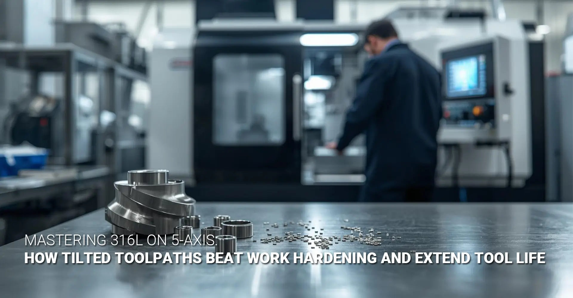
Machining 316 Stainless Steel on 5-Axis: How the Right Tilt Angle Cuts Tooling Costs by 30%?
If your shop is burning through carbide, fighting scrap, and losing time on 316 stainless — the problem might not be your tools. It might be your angle.
Machining 316 stainless steel is one of the hardest challenges in precision manufacturing. The material fights back. It work-hardens. It traps heat. And it destroys expensive carbide inserts faster than almost any other common alloy. Many shops accept this as the cost of doing business. But the truth is — a simple change in tool engagement angle, made possible by 5-axis machining, can cut tooling costs by 30 to 50% and reduce cycle times by nearly half.
This article breaks down exactly how that works, with real numbers and actionable advice you can use today.

⚡ Quick Answer: What You Need to Know Right Now
The core fix: Tilt your tool 15–20° on a 5-axis machine. This reduces the contact arc between the cutter and the workpiece, which lowers heat, prevents work hardening, and extends carbide tool life — often cutting total cost per part by 30–50%.
| Problem | Cause | 5-Axis Tilt Solution |
|---|---|---|
| Rapid carbide wear | Full tool engagement = excess heat | Reduced contact arc lowers heat at cutting edge |
| Work hardening | Rubbing instead of shearing | Positive chip thickness maintained at all depths |
| High scrap rate | Unpredictable tool failure | Consistent, controlled toolpaths reduce surprises |
| Long cycle times | Multiple passes, frequent insert changes | Fewer passes, longer insert life |
| High cost per part | Scrap + tooling + rework | 30–50% reduction documented in case studies |
So why do so many shops still run 316 stainless the same way they run aluminum or mild steel? Because the problem isn't visible until it's expensive. Below, we'll walk through the science, the strategy, and the real-world savings — section by section — so you can stop losing money on stainless and start machining it with confidence.
Table of Contents
- Why Is Machining 316 Stainless Steel So Difficult?
- What Does Tilting the Tool Actually Do to Heat and Chip Load?
- Real Cost Savings on 316L Chemical Fittings — A Case Study
- How Do You Apply 5-Axis Tilt Strategies on 316L — Practically?
- Conclusion
Why Is Machining 316 Stainless Steel So Difficult?
Every machinist who has run a job in machining 316 stainless steel knows that sinking feeling — the one that comes when you hear the pitch of the spindle change, or when you pull a finished part and see chatter marks, or when you check the insert and find it's already worn after only a handful of parts. The material seems to punish you for every mistake, and sometimes even for doing things right. But the difficulty of 316 stainless is not random. It has two very specific causes: work hardening and heat buildup. Understanding both is the first step to solving the problem.
316L vs. Common Alloys at a Glance
| Property | 316L Stainless | 304 Stainless | Mild Steel (1018) |
|---|---|---|---|
| Machinability Rating | ~35% | ~45% | 78% |
| Work Hardening Tendency | Very High | High | Low |
| Heat Conductivity | Low | Low | High |
| Corrosion Resistance | Excellent | Good | Poor |
| Typical Application | Chemical fittings, medical | Food equipment | General fabrication |
Key takeaway: 316L has one of the lowest machinability ratings of any common alloy. Its low heat conductivity means heat stays in the part — not the chip.
The Two Villains Explained
Work hardening stainless steel is not a defect in the material. It is a property. When 316 stainless is deformed by cutting — or worse, rubbed without cutting — the crystal structure of the metal changes. The surface becomes harder. In practical terms, this means:
- Pass 1: Tool engages soft base metal → surface left slightly work-hardened
- Pass 2: Tool now cuts into harder material → tool wears faster → more heat generated
- Pass 3: Surface is even harder → tool fails
This spiral is especially dangerous during finishing passes. If your chip thickness drops below the cutting edge radius — even briefly — the tool stops shearing and starts rubbing. That rubbing generates intense heat with almost no material removal. The result is a work-hardened layer that the next pass must cut through.
Heat dissipation machining becomes critical here because 316L has roughly half the thermal conductivity of mild steel. In most metals, heat escapes through the chip. In stainless, much of it stays in the workpiece — and in your tool. This is why conventional 3-axis milling, with full bottom-of-tool engagement, creates such extreme conditions at the cutting edge.
The solution is not simply running slower or using more coolant. The solution is changing the geometry of engagement — which is exactly what 5-axis tilt enables. For a broader look at how CNC machining handles difficult materials across industries, see our guide to stainless steel in CNC machining.
What Does Tilting the Tool Actually Do to Heat and Chip Load?
The physics of tool engagement angle optimization are straightforward once you see them. When a flat-end mill runs perpendicular to the workpiece surface — as it does in standard 3-axis milling — the entire bottom face of the tool contacts the material. That means maximum contact area, maximum friction, maximum heat, and the lowest possible chip thickness at the center of the tool (which is essentially zero). Now tilt that same tool 15° forward in the feed direction. Suddenly, the contact arc shrinks dramatically. The center of the tool lifts away from the surface. Heat generation drops. And the chip gets thicker and more consistent — which means the tool is actually cutting, not rubbing.
From 90° to 15° — What Changes
The single most important number in 5-axis stainless machining: 15–20° That is the lead angle (tool tilt in the feed direction) that delivers the best balance of heat reduction, chip thickness, and surface quality on 316L.
| Tilt Angle | Contact Arc | Heat Generated | Chip Thickness | Tool Life |
|---|---|---|---|---|
| 0° (flat) | 100% (full face) | Very High | Near zero at center | Shortest |
| 10° | ~60% | High | Improving | Moderate |
| 15–20° | ~30–40% | Low | Consistent & positive | Longest |
| 30°+ | ~15% | Very Low | May cause vibration | Risk of chatter |
Chip Thinning, Coolant Access, and Why Any Tilt Beats None
Chip thinning is the mathematical consequence of tilting the tool. When a ball-nose or end mill is tilted, the effective cutting diameter at the point of engagement changes. The chip produced is thinner relative to the programmed feed per tooth — which means you can increase feed rate to compensate, maintaining a productive chip load while generating less heat. Experienced 5-axis programmers use a chip thinning factor (typically 0.6–0.8x for a 15° lead angle) to recalculate true chip load and optimize feeds accordingly.
Beyond chip thinning, tilt also dramatically improves coolant delivery. In a flat 3-axis cut, the tool's flutes push coolant away from the exact cutting zone. With a tilted tool, an open space forms under the cutter — and high-pressure through-spindle coolant (1,000+ PSI) can reach the point of engagement directly. This flushes chips and reduces thermal buildup at the same time. The combination of tilt + high-pressure coolant has been shown to increase carbide tool life stainless by 200–300% compared to conventional flood-only 3-axis milling.
Remember: Any tilt is better than zero tilt. Even a 5° lead angle provides measurable heat reduction on 316L. You do not need to start at 20° — just start tilting.
For complex component geometries where 5-axis tilt provides the most value — such as aerospace brackets or industrial machinery housings — the thermal advantage compounds because more surfaces can be reached in a single setup, eliminating the re-clamping that introduces vibration and inconsistency.
Real Cost Savings on 316L Chemical Fittings — A Case Study?
Theory is useful. Numbers are better. Stainless steel chemical fittings are one of the most demanding applications for 316L machining — they require tight tolerances, excellent surface finish, and consistent thread quality, all in a material that resists every one of those requirements. They are also high-value parts where scrap is extremely expensive. This makes them the perfect test case for comparing 3-axis flat milling against a proper 5-axis toolpath strategy.
Side-by-Side Results
| Metric | 3-Axis Flat Milling | 5-Axis Tilted Strategy |
|---|---|---|
| Cycle Time per Part | 25 minutes | 12 minutes |
| Inserts Used per Part | 2 corners | 1 corner |
| Scrap Rate | ~15% | ~2% |
| Surface Finish (Ra) | 1.6–3.2 µm (inconsistent) | 0.8–1.6 µm (consistent) |
| Tooling Cost Reduction | Baseline | 30–50% lower |
| Delivery Predictability | Low (tool failures disrupt schedule) | High (predictable insert life) |
Bottom line: The 5-axis job takes less than half the time and uses half the tooling — while producing a better part with a fraction of the scrap.

Total Landed Cost per Part — The Number That Matters
Many procurement managers make decisions based on hourly machine rate. This is the wrong metric for difficult materials. Here is why:
- A 3-axis shop quotes $90/hour. The job takes 25 minutes per part (0.42 hours). That is $37.80 in machine time per part — before tooling or scrap.
- Add 2 insert corners at $8 each = $16 in tooling.
- Add 15% scrap: for every 100 parts, 15 are scrapped. Add $5.67 per good part in scrap cost.
- 3-axis total: ~$59.47 per good part.
Now the 5-axis shop:
- Quotes $150/hour. Job takes 12 minutes (0.20 hours). Machine cost = $30 per part.
- 1 insert corner at $8 = $8 in tooling.
- 2% scrap = $0.61 per good part.
- 5-axis total: ~$38.61 per good part.
That is a 35% lower cost per part stainless steel — despite a 67% higher hourly rate. This is why procurement teams that evaluate suppliers on total landed cost consistently choose capable 5-axis shops for 316L work.
When requesting quotes, always ask: "What is your expected scrap rate and insert life per corner on this geometry in 316L?" A supplier who answers with real numbers understands what they are doing. For rapid prototyping in 316L — where time-to-first-good-part is critical — the advantage of 5-axis tilt is even more pronounced, since failed inserts on a prototype job mean expensive delays.
How Do You Apply 5-Axis Tilt Strategies on 316L — Practically?
Understanding why tilt works is one thing. Knowing how to implement it on your next job is another. High efficiency machining stainless does not happen automatically just because you have a 5-axis machine. It requires deliberate toolpath choices, the right CAM settings, and a clear understanding of when to use constant tilt versus variable tilt. This section gives you the practical framework — whether you are programming the job yourself or evaluating a supplier's approach.
Snippet Paragraph: 5-Axis Stainless Steel Optimization Checklist
Use this checklist before running any 316L job on a 5-axis machine:
✅ Set lead angle 15–20° — Start here. This is the single most impactful change you can make.
✅ Use trochoidal milling stainless for deep pockets and slots — Circular toolpaths with small radial engagement keep chip load consistent and allow the tool to cool between passes. Combine trochoidal motion with tilt for maximum thermal control in deep features.
✅ Run through-spindle coolant at 1,000+ PSI — Tilt opens up access to the cutting zone. High-pressure coolant takes advantage of that access to flush chips and reduce temperature.
✅ Confirm chip thinning factor in your CAM software — Most modern CAM systems (Mastercam, Hypermill, Siemens NX) allow you to input lead angle and auto-calculate chip thinning. Verify the actual chip load at the tool tip — not just the programmed feed per tooth.
✅ Avoid tapping 316L — use thread milling — Taps break easily in work-hardened stainless. A carbide single-form thread mill on a helical path (one tooth engaged at a time) is safer and more consistent. Maintain perfect tool orientation with the 5-axis machine for small threads.
✅ Ask your supplier for insert life data — Request the number of good parts per insert corner on a similar 316L job. This reveals whether they are actually running tilt strategies or just programming it like aluminum.
Constant Tilt vs. Variable Tilt, and Lead vs. Tilt Angle
Constant tilt means the lead angle stays fixed throughout the toolpath — for example, always 15° in the feed direction. This is simple to program and works well on relatively flat or gently curved surfaces. It is the best starting point for shops new to 316L 5-axis machining.
Variable tilt means the CAM system dynamically adjusts the lead angle as the tool moves across complex geometry — maintaining the optimal engagement arc even as the surface normal changes. This is more complex to program but delivers the most consistent results on freeform surfaces, deep pockets, and undercuts. For high-value chemical fittings with multiple compound curves, variable tilt is worth the programming investment.
Don't confuse lead angle and tilt angle:
- Lead angle = tilt in the feed direction (forward/backward). This is what reduces contact arc and improves chip thickness. This is the one that matters most for heat control.
- Tilt angle (side tilt) = tilt perpendicular to the feed direction. This is used to avoid collisions or improve surface finish on specific geometries — but it does not provide the same thermal benefit as lead angle.
For shops running automotive components in 316L stainless — exhaust manifold flanges, sensor housings, brake system fittings — variable tilt combined with trochoidal roughing and tilted finishing passes represents the current best practice. The thermal and tool-life benefits scale directly with part complexity and material volume removed.
Finally, for any shop evaluating a CNC machining service for 316L work, the questions in this checklist should form the basis of your supplier qualification process. A capable shop will welcome the specificity. A shop running 316L like mild steel will struggle to answer.
Conclusion
Machining 316 stainless steel does not have to be a fight. The material is challenging — that is true. But the challenge has a clear, well-understood solution: control the heat, and the work hardening takes care of itself. And the best tool for controlling heat is a tilted toolpath on a 5-axis machine.
Here is what to remember:
- Work hardening and heat are the two root causes of every frustrating 316L machining problem. They are linked — heat drives hardening, hardening increases heat.
- Tilting the tool 15–20° (lead angle) dramatically reduces the contact arc. Less contact = less friction = less heat = less work hardening = longer tool life.
- Real-world case studies show 30–50% tooling cost reduction and cycle time cuts of 40–50% when moving from flat 3-axis to tilted 5-axis strategies on the same 316L parts.
- Total cost per part — not hourly rate — is the right metric when evaluating 5-axis vs. 3-axis shops for stainless work.
- Any tilt is better than no tilt. Start at 15°, confirm your chip thinning factor in CAM, run high-pressure coolant, and avoid tapping. Those four steps alone will transform your 316L results.
- Ask your supplier the right questions. Concrete answers about lead angle, chip load, and insert life data separate experienced 5-axis shops from shops that simply own 5-axis machines.
The next time you see a 316L job on your schedule — or you are sending one out for quote — remember: the angle is the answer.
Recommended External Resources
[work hardening stainless steel][^2]
[tool engagement angle optimization][^3]
[heat dissipation machining][^4]
[stainless steel chemical fittings][^5]
[5‑axis toolpath strategy][^6]


