How to Achieve Ra 0.4 Mirror Finish on Aluminum Through Milling Alone?
How to Achieve Ra 0.4 Mirror Finish on Aluminum Through Milling Alone?

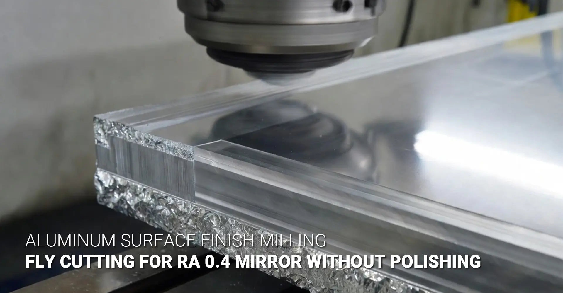
Are you trying to create stunning mirror finishes on aluminum parts without spending hours on polishing? Many machinists believe achieving Ra 0.4 surface quality requires extensive post-processing. However, with the right fly cutting technique and setup, you can mill 6061 aluminum to a perfect mirror finish directly off the machine. Moreover, this approach saves time, reduces costs, and delivers consistent results across production runs. This guide shows you exactly how to master aluminum surface finish milling for high-end applications.
Quick Answer: What You Need to Know
✓ Key Takeaways: Mirror Finish Aluminum Milling
| Parameter | Specification |
|---|---|
| Surface finish achievable | Ra 0.4 or better without polishing |
| Best method | Fly cutting with single-point inserts |
| Ideal material | 6061-T6 aluminum alloy |
| Spindle speed range | 3000-6000 RPM |
| Feed rate | 0.01-0.03mm/rev |
| Tool runout limit | Under 0.002mm |
| Flatness achievable | 0.01-0.02mm over 300x300mm panels |
| Visual indicator | Rainbow interference pattern |
Now that you know mirror finishes are possible through milling alone, let's explore why certain industries demand this level of quality. Furthermore, we'll break down the specific techniques that separate amateur attempts from professional results. By the end of this article, you'll understand exactly how to set up your machine, select the right tools, and dial in parameters for flawless results.
Table of Contents
- Why Do Hi-Fi Panels and Decorative Parts Need Mirror-Like Aluminum Surfaces?
- What Makes Fly Cutting Better Than Face Milling for Aluminum Mirror Finishes?
- Which Cutting Parameters Deliver Ra 0.4 Surface Quality on 6061 Aluminum?
- How Can You Prevent Common Problems When Milling Mirror Aluminum Finishes?
- Conclusion
Why Do Hi-Fi Panels and Decorative Parts Need Mirror-Like Aluminum Surfaces?
When you walk into a high-end audio showroom, the first thing that catches your eye is usually the flawless finish on equipment faceplates. These aren't just polished surfaces—they're precision-machined components that demand exceptional quality. In fact, the finish quality directly impacts both product perception and long-term performance.
Industries demanding mirror aluminum finishes include:
- Audio equipment manufacturing - amplifiers, receivers, and speaker housings
- Consumer electronics - smartphone frames, laptop chassis, and tablet backs
- Architectural hardware - elevator panels, door handles, and decorative fixtures
- Medical devices - surgical instrument housings and diagnostic equipment covers
- Automotive trim - interior accents and exterior badges

Beyond aesthetics, mirror finishes serve critical functional purposes. First, they eliminate microscopic scratches that trap dirt, grease, and contaminants. Second, the smooth surface resists corrosion better than rougher finishes because there are fewer surface irregularities where oxidation can start. Third, these surfaces are easier to clean and maintain over the product's lifetime.
The electronics manufacturing sector particularly values mirror finishes because they signal premium quality to consumers. Research shows that customers associate flawless surfaces with superior engineering and reliability. Additionally, in applications like medical equipment, smooth surfaces are essential for sterilization protocols. When surgical instruments or diagnostic tools have rough surfaces, bacteria can hide in microscopic valleys, creating serious health risks.
High aesthetic CNC aluminum finish requirements typically specify Ra values between 0.2 and 0.4 micrometers. For context, standard machined surfaces usually range from Ra 1.6 to Ra 3.2. Achieving finishes four to eight times smoother requires completely different approaches to tooling, parameters, and machine setup. Traditional face milling operations simply cannot reach these quality levels consistently.
What Makes Fly Cutting Better Than Face Milling for Aluminum Mirror Finishes?
The debate around face mill vs fly cutter surface finish quality has a clear winner when mirror finishes are required. Understanding why requires looking at the fundamental mechanics of each cutting method. Consequently, choosing the right approach from the start saves countless hours of trial and error.
Face mills employ multiple cutting inserts arranged around a central body. As the tool rotates, each insert takes a cut in rapid succession. While this creates efficient material removal, it also introduces several problems for high-quality finishes. Each insert has slightly different runout, cutting edge geometry, and wear patterns. Therefore, the surface shows subtle ridges and valleys corresponding to each insert's path.
In contrast, fly cutters use a single cutting point mounted in a holder. This single-point tool generates a continuous, uninterrupted spiral pattern across the workpiece. Since only one cutting edge does all the work, there are no variations between multiple inserts. The result is dramatically improved flatness and consistency.
Here's a detailed comparison of both methods:
Face Milling Characteristics:
- Multiple cutting edges create interrupted cuts
- Each insert contributes cumulative runout errors
- Typical best finish is Ra 1.6 to Ra 3.2
- Faster material removal rates
- Less sensitive to machine rigidity
- Better for roughing and semi-finishing operations
Fly Cutting Characteristics:
- Single cutting edge produces continuous cuts
- Only one runout source to control
- Achievable finish is Ra 0.2 to Ra 0.4
- Slower material removal (finishing only)
- Requires excellent machine rigidity
- Ideal for final finishing passes
When you're pursuing fly cutting aluminum mirror finish quality, the cutting edge geometry becomes crucial. The insert must have a large nose radius (typically 1.5mm to 3mm) and a perfectly honed edge. Diamond-coated carbide, polycrystalline diamond (PCD), or cubic boron nitride (CBN) inserts work best. Meanwhile, standard sharp carbide inserts tend to create built-up edge problems with aluminum.
Aluminum face milling flatness is limited by the number of cutting edges and their individual runout. Even with perfectly balanced face mills, you'll struggle to achieve better than 0.05mm flatness over large areas. Fly cutting, when properly executed, delivers 0.01-0.02mm flatness over 300x300mm panels. This difference matters enormously for applications like Hi-Fi faceplates where visual perfection is expected.
The spiral pattern left by fly cutting also contributes to the characteristic rainbow appearance. As the tool sweeps across the surface in a precise spiral, it creates microscopically consistent peaks and valleys. These features are so uniform that light interference creates the rainbow pattern—essentially a visual proof of perfect surface generation. You simply cannot achieve this effect with face milling because the multiple inserts create irregular patterns.
Which Cutting Parameters Deliver Ra 0.4 Surface Quality on 6061 Aluminum?
Getting to Ra 0.4 aluminum milling quality requires precision in every parameter. Unlike conventional machining where you have a wide operating window, mirror finishing demands tight control. Fortunately, once you understand the relationships between speed, feed, and depth of cut, the process becomes highly repeatable.
The core parameter formula for mirror aluminum finishes:
For fly cutters with diameters between 10-20mm on 6061-T6 aluminum, your starting point should be:
- Spindle speed: 3000-6000 RPM
- Feed rate: 0.01-0.03mm per revolution
- Depth of cut: 0.05-0.15mm (finishing passes only)
- Tool nose radius: 1.5-3.0mm
Let's break down why each parameter matters. Spindle speed determines the cutting velocity at the tool's edge. Higher speeds generally produce better finishes on aluminum because they reduce the tendency for material to weld onto the cutting edge. However, speeds that are too high can cause heat buildup and dimensional issues. Therefore, 3000-6000 RPM provides the sweet spot for most setups.
The feed rate for mirror aluminum finish operations is critical. Feed per revolution (not feed per minute) gives you better control because it accounts for spindle speed variations. At 0.01-0.03mm/rev, you're taking very fine cuts that leave minimal tool marks. Each pass of the cutting edge removes just enough material to create a fresh, unmarked surface.
Calculating your ideal feed rate:
- Measure your fly cutter diameter (example: 16mm)
- Calculate cutting speed: π × diameter × RPM ÷ 1000 = meters/min
- For 16mm at 4500 RPM: 3.14 × 16 × 4500 ÷ 1000 = 226 meters/min
- Set feed at 0.02mm/rev × 4500 RPM = 90mm/min table feed
Depth of cut for finishing should never exceed 0.15mm. In fact, many machinists achieve best results with depths of just 0.05-0.08mm. These shallow cuts minimize cutting forces, reduce vibration, and prevent deflection. Remember, you're not trying to remove material quickly—you're trying to create a perfect surface.
Coolant strategy matters significantly:
Different coolant approaches affect the final finish quality. Water-based flood coolant can cause thermal shock on aluminum, potentially creating micro-cracks in the freshly cut surface. Additionally, coolant residue sometimes leaves stains that are difficult to remove from mirror finishes.
Better options include:
- Straight cutting oil - excellent lubricity, no water-based residue
- High-pressure mist - keeps chips clear while minimizing fluid contact
- Compressed air blast - dry cutting works well for final mirror passes
- No coolant - viable for very light finishing cuts on rigid machines
For 6061 aluminum mirror milling specifically, the T6 temper provides ideal conditions. The material is hard enough to resist the cutting edge but soft enough to avoid excessive tool wear. T6 temper also has lower ductility than softer tempers, which reduces the tendency for material to smear rather than shear cleanly.
Stepdown strategy for achieving mirror finishes:
Don't jump directly to mirror finish parameters from rough machining. Instead, use this progression:
- Roughing pass: Remove bulk material with face mill at Ra 3.2-6.3
- Semi-finishing: Reduce to Ra 1.6 with face mill or larger fly cutter
- Pre-finishing: Achieve Ra 0.8 with fly cutter at moderate feeds
- Mirror finishing: Final pass at 0.05mm depth with optimal parameters
This stepped approach ensures you're not asking the finishing pass to do too much work. When the pre-finish is already at Ra 0.8, the final pass only needs to remove a few microns to reach Ra 0.4 or better.
Advanced parameter optimization:
Once you have baseline parameters working, fine-tune based on results. If you see chatter marks, reduce feed rate or increase spindle speed. When you notice built-up edge, increase cutting speed or switch to a sharper insert. For decorative aluminum panel milling where appearance is paramount, don't hesitate to run multiple finish passes at slightly different parameters to achieve perfection.
Professional CNC machining services often maintain parameter libraries for different materials and finish requirements. Building your own reference database helps ensure consistency across jobs and operators.
How Can You Prevent Common Problems When Milling Mirror Aluminum Finishes?
Even with perfect parameters, several common issues can ruin mirror finishes. Fortunately, these problems have well-understood causes and solutions. Identifying and correcting them quickly separates successful mirror finishing from frustrating failures.
The three main problems are:
- Built-up edge (BUE) - aluminum welding to the cutting tool
- Chatter marks - vibration patterns on the finished surface
- Tool runout - wobbling that creates spiral ridges
Built-Up Edge Prevention:
Aluminum's natural tendency to adhere to cutting tools creates the biggest challenge. When aluminum welds onto the cutting edge, it acts like an irregular cutting tool, creating poor finishes and dimensional errors. You'll recognize BUE by rough, torn surface texture instead of the smooth mirror you expect.
Solutions for BUE include:
- Increase cutting speed by 20-30% to raise edge temperature
- Use sharper tools with polished rake faces
- Switch to coated inserts (TiN, TiAlN, or diamond-coated)
- Apply lighter cutting pressure through reduced depth of cut
- Consider PCD (polycrystalline diamond) inserts for production runs
The rainbow pattern aluminum machining effect actually helps diagnose BUE problems. If the rainbow pattern is interrupted or inconsistent, built-up edge is likely forming and breaking off periodically. A perfect mirror finish shows continuous, even color bands across the entire surface.
Eliminating Chatter:
Chatter appears as regular wave patterns or rings on the finished surface. This vibration occurs when cutting forces excite natural resonance frequencies in the machine, workpiece, or tooling system. Even microscopic vibrations become visible on mirror finishes.
Chatter elimination strategies:
- Increase machine rigidity - tighten gibs, check way wear, verify foundation
- Improve workholding - vacuum tables work better than clamps for thin panels
- Reduce tool overhang - keep fly cutter holders as short as possible
- Dampen vibrations - add mass to tool holder or use dampened boring bars
- Change cutting frequency - vary spindle speed slightly to avoid resonance
For large decorative panels, workholding becomes critical. Clamps create stress points that can telegraph through thin aluminum, causing localized deformation. Vacuum tables distribute clamping force evenly across the entire part, resulting in superior flatness. Many shops specializing in mirror finishes invest in dedicated vacuum systems for this reason.
Controlling Tool Runout:
Runout—the wobbling of the cutting tool as it rotates—directly translates into surface irregularities. While you can tolerate 0.01-0.02mm runout for general machining, mirror finishing requires keeping runout under 0.002mm. This precision demands careful attention to tool mounting and measurement.
Steps to minimize runout:
- Clean all tapers - remove every speck of debris from tool holders and spindle taper
- Measure runout - use dial indicator at tool tip before each setup
- Index the holder - rotate tool holder in spindle to find lowest runout position
- Tighten properly - use correct pull stud torque and drawbar pressure
- Replace worn holders - damaged or worn tool holders cannot achieve precision
Professional machinists typically measure runout at both the holder body and the cutting edge. Total runout at the cutting edge should be under 0.002mm (2 microns). If you measure higher values, check each component systematically until you find the source.
Machine Requirements:
Not every CNC mill can produce mirror finishes. Consumer-grade desktop machines lack the rigidity and precision needed for Ra 0.4 results. Look for these characteristics in suitable machines:
- Heavy, rigid construction - cast iron base with thick walls
- Precision spindles - well-maintained with minimal runout
- Quality ways and bearings - linear guides or properly scraped box ways
- Solid foundation - machine mounted on proper foundation, not wooden benches
- Thermal stability - temperature-controlled environment prevents expansion
Industrial machinery designed for production work typically meets these requirements. Bridge mills, large gantry machines, and jig borers excel at mirror finishing because they prioritize rigidity over speed.
Quality Verification:
How do you know when you've achieved Ra 0.4? While the rainbow pattern provides a good visual indicator, proper verification requires measurement. Portable profilometers can measure surface roughness directly on the machine. These instruments typically cost $3,000-$15,000 but provide objective data.
For production environments, consider these verification methods:
- Contact profilometry - stylus-based measurement, very accurate
- Optical profilometry - non-contact laser measurement
- Visual comparison - compare to reference standards under consistent lighting
- Touch verification - experienced machinists can feel finish differences
The rainbow interference pattern itself serves as a valuable quality indicator. Perfect finishes show even, consistent color bands with smooth gradients. Interrupted patterns, spotty colors, or dull areas indicate problems with cutting consistency. Understanding different surface finish options helps you specify the right quality level for each application.
Troubleshooting Workflow:
When mirror finishes aren't meeting expectations, follow this systematic diagnosis:
- Examine the surface under bright light - identify pattern of defects
- Measure tool runout - confirm under 0.002mm at cutting edge
- Check for built-up edge - inspect cutting tool under magnification
- Verify parameters - confirm speeds, feeds, and depths are correct
- Test machine rigidity - check for loose components or worn ways
- Review workholding - ensure part is fully supported and stress-free
Most problems trace back to one of these six areas. By working through them methodically, you'll identify root causes rather than just treating symptoms.
Scaling to Production:
Once you achieve reliable mirror finishes on prototype parts, maintaining that quality in production requires process control. Document every detail of your successful setup: tool specifications, holder position, parameter values, coolant type, and even ambient temperature. Small variations that don't matter for conventional machining can ruin mirror finishes.
Consider creating a dedicated setup for mirror finishing jobs. Keeping certain tools, holders, and even specific spindles reserved for this work ensures consistency. Some shops mark their best-performing tool holders and spindle positions specifically for critical finishing operations.
Conclusion
Achieving Ra 0.4 mirror finishes on aluminum in CNC machining through milling is completely realistic when you combine proper fly cutting techniques with precise machine setup. By controlling spindle speeds between 3000-6000 RPM, maintaining feed rates of 0.01-0.03mm per revolution, and keeping tool runout under 0.002mm, you can produce stunning rainbow-pattern surfaces without any polishing steps.
The key insights to remember include choosing fly cutting over face milling for superior flatness, using stepped finishing passes to build up to mirror quality, and maintaining rigorous control over built-up edge, chatter, and runout. Start with the parameters outlined above, measure your results carefully, and adjust based on your specific machine's capabilities.
With practice and attention to detail, you'll consistently deliver the flawless finishes that high-end applications demand. Whether you're machining Hi-Fi equipment panels, consumer electronics housings, or decorative architectural components, these techniques provide the foundation for exceptional results.
Recommended External Resources
[Aluminum surface finish milling][^1]
[Fly cutting aluminum mirror finish][^2]
[face mill vs fly cutter surface finish][^3]
[rainbow pattern aluminum machining][^5]
[high aesthetic CNC aluminum finish][^6]
------
[^1]: A comprehensive engineering guide to surface roughness (Ra, Rz) in CNC milling, covering how tool geometry, feed rates, and machine rigidity directly impact the final surface quality of aluminum components.
[^2]: A technical deep-dive into using PCD (Polycrystalline Diamond) fly cutters to achieve optical-grade mirror finishes on non-ferrous metals, explaining why single-point machining is superior for creating highly reflective, flat surfaces.
[^3]: A professional technical article comparing multi-insert face mills with single-point fly cutters, explaining why fly cutters often produce superior, mirror-like finishes on aluminum by eliminating the height variations found in multi-tooth tools.
[^4]: A detailed manufacturing guide for achieving Ra 0.4 micron finishes, highlighting the necessary cutting parameters (high speed, fine feed, and light cuts) and explaining why this "precision" level is the highest standard offered in CNC milling before secondary grinding.
[^5]: A scientific research paper explaining the "rainbow trapping" effect in metallic structures, detailing how precise micro-groove depth and grating periods created during machining can manipulate light to produce visible interference colors and diffraction patterns on metal surfaces.
[^6]: A professional engineering guide on achieving "unparalleled" aesthetic finishes on aluminum, focusing on the use of Monocrystalline Diamond (MCD) tooling and high-speed machining strategies to produce mirror-like, optically clear, and highly decorative surface textures without post-processing.


