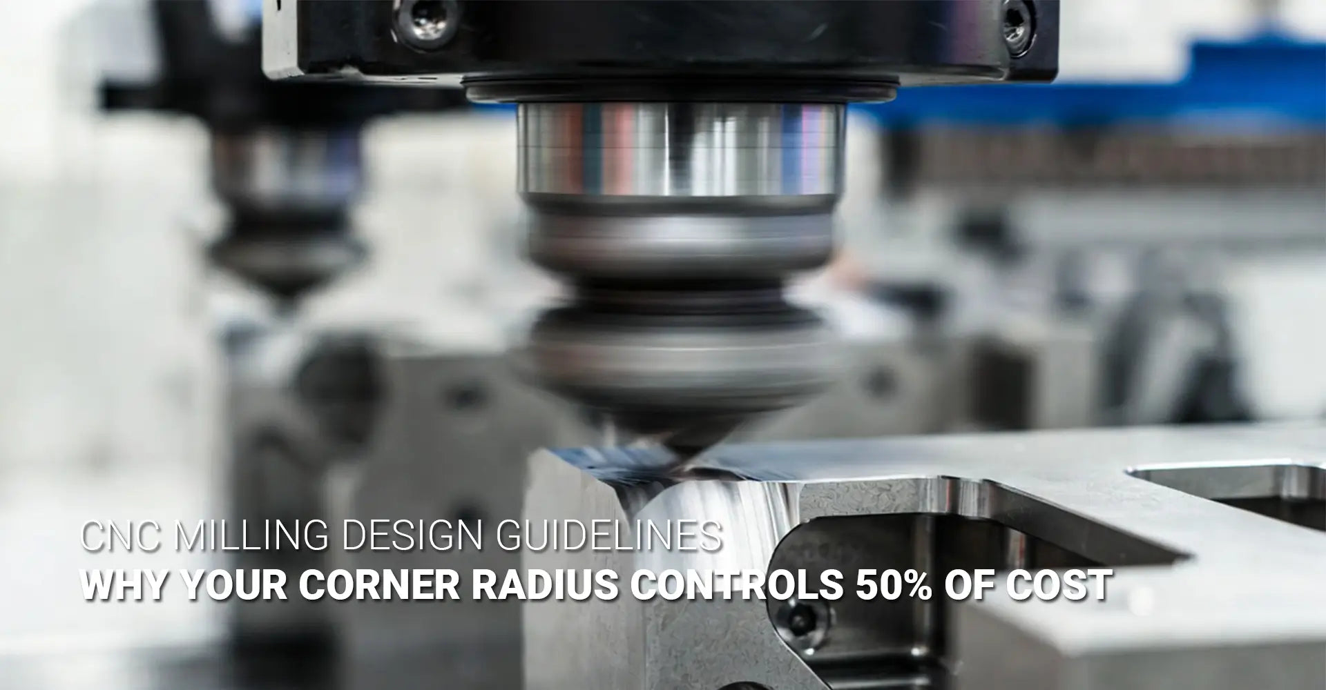
Why Does Corner Radius Control Half Your CNC Milling Budget?
Why Does Corner Radius Control Half Your CNC Milling Budget?

Every day, design engineers submit CAD files with perfectly sharp 90-degree internal corners, unaware they've just doubled their manufacturing quote. The disconnect between design intent and machining reality creates a persistent budget drain across industries—from automotive prototyping to industrial machinery production. A single corner specification, often treated as a minor detail, can swing project costs by 30-50% without changing part functionality. Understanding this relationship is the fastest path to cost-effective design.
The culprit behind inflated machining costs isn't complex geometry or exotic materials—it's the fundamental physics of rotary cutting tools. Round endmills cannot physically produce sharp internal corners without significant time penalties, undersized tooling that risks breakage, or expensive secondary operations. When designers specify R0.5mm corners where R5.0mm would work equally well, they unknowingly force machinists into slow, high-risk strategies that inflate both cycle time and scrap rates.
This cost multiplier doesn't stem from machinist preferences or arbitrary shop standards. It's rooted in the mechanical constraints of tool geometry, material removal rates, and the inescapable mathematics of length-to-diameter ratios. By examining why CNC mills struggle with sharp corners and learning proven design strategies that eliminate these bottlenecks, engineers can specify parts that machine efficiently without sacrificing functional requirements. The following sections break down the technical reality behind corner-related costs and provide actionable guidelines that work across materials and applications.
Table of Contents
- Why Can't CNC Mills Cut Sharp Internal Corners?
- What Role Does Tool Length-to-Diameter Ratio Play in Corner Costs?
- How Do Dogbone Features Solve the Sharp Corner Problem?
- Which Corner Radius Specifications Actually Save Money?
Why Can't CNC Mills Cut Sharp Internal Corners?
The challenge with sharp internal corners begins with basic endmill geometry. Unlike lathe tools or broaches that use fixed cutting edges, milling cutters are cylindrical tools that rotate at high speeds while plunging into material. The cutting edges follow the circular perimeter of the tool body, which means the smallest radius the tool can physically create equals the tool's radius itself. For a 10mm diameter endmill, the tightest internal corner possible is 5mm—the tool simply cannot reach any closer to a true 90-degree vertex.
This geometric limitation forces machinists into uncomfortable compromises when faced with sharp corner CNC milling problems. To approach tighter radii, they must switch to progressively smaller diameter tools. A 2mm corner requires a 4mm endmill maximum, a 1mm corner needs a 2mm tool, and R0.5mm corners demand tiny 1mm cutters that are fragile, expensive, and painfully slow. Each downsizing step reduces material removal rates and increases the risk of tool deflection or catastrophic failure.
Machinists typically resort to three workarounds when drawings specify corners their standard tooling can't accommodate. The first approach uses multiple passes with progressively smaller tools—starting with an 8mm endmill for bulk material removal, stepping down to 4mm for semi-finishing, and finally using a 2mm tool for the corner detail. This strategy works but triples programming time and machine hours. The second method employs extremely small endmills from the start, accepting slower feed rates and frequent tool changes as broken cutters pile up. The third option, manual corner finishing with files or die grinders, introduces human error and labor costs that often exceed the machining time itself. None of these solutions are ideal for production environments where CNC machining service providers need to maintain tight tolerances while keeping costs competitive. The smart alternative is designing corners that match available tooling from the beginning.
What Role Does Tool Length-to-Diameter Ratio Play in Corner Costs?
Beyond simple tool diameter, the length-to-diameter ratio (L:D) governs how deep an endmill can cut before mechanical instability makes quality parts impossible. A stubby 10mm endmill with 20mm of flute length operates at 2:1 L:D—rigid, stable, and capable of aggressive cutting parameters. That same 10mm tool extended to 100mm flute length becomes a 10:1 L:D nightmare that chatters, deflects, and produces poor surface finishes even at conservative speeds. This ratio directly impacts the L:D ratio milling cost because longer, skinnier tools require dramatically slower feed rates and shallower depth of cut to avoid catastrophic failure.
The cost implications become severe when corner specifications force small-diameter, long-reach tooling. Cutting a 25mm deep pocket with R0.5mm corners might require a 1mm diameter endmill extended 30mm (30:1 L:D)—far beyond practical limits for most materials. Machinists must then resort to multiple shallow passes, ultra-conservative parameters, or expensive specialty tooling like high-stiffness carbide with damping coatings. Meanwhile, the same pocket with R3.0mm corners accommodates a 6mm endmill at 5:1 L:D, cutting at full depth in a fraction of the time.
Real-world data illustrates the dramatic cost swing. Consider a 50mm x 50mm x 20mm pocket in 6061 aluminum—a common requirement in custom CNC milling services. With R5.0mm corners, the machinist selects a 10mm endmill (2:1 L:D), running at 8,000 RPM and 1,200mm/min feed rate with 10mm axial depth. Total cycle time: approximately 12 minutes. Now specify R0.5mm corners on that same pocket. The shop must use a 1mm endmill at 12:1 L:D minimum, dropping to 3,000 RPM and 180mm/min feed with 2mm maximum depth of cut to prevent tool breakage. The same geometry now requires 45-55 minutes—nearly 4x longer for identical material removal volume. The milling cost vs corner radius relationship isn't linear; it's exponential once you cross critical L:D thresholds. Material hardness amplifies this effect: what works in aluminum becomes impossible in hardened tool steel without switching to entirely different processes like EDM.
How Do Dogbone Features Solve the Sharp Corner Problem?
The dogbone corner CNC technique represents an elegant compromise between visual sharpness and machining efficiency. Rather than attempting to cut into the actual corner vertex, the design adds small circular reliefs—typically matching the endmill radius—that allow standard-diameter tools to clear completely while maintaining the sharp appearance needed for part function. The name comes from the distinctive bone shape these reliefs create when viewed from above, with the circular cutouts resembling the knobbed ends of a dog bone at each corner of a rectangular pocket.
From a manufacturing standpoint, dogbone features transform problematic geometry into routine operations. A pocket that would otherwise require three different tool sizes can be completed with a single appropriately-sized endmill, cutting programming time, tool changes, and cycle time simultaneously. The visual result appears acceptably sharp for most applications—mating parts fit correctly, assembly clearances work as intended, and only close inspection reveals the small relief cuts. For production volumes where every minute of machine time compounds across hundreds or thousands of parts, implementing bone shape corner clearance can reduce per-part costs by 40-60% compared to attempting true sharp corners.
Implementing dogbone features requires minimal design effort but delivers maximum machining benefit. The relief diameter typically matches the intended cutting tool—if you're using a 6mm endmill, add 3mm radius reliefs at each corner. Most CAD packages include automated dogbone generation plugins that apply these reliefs to selected corners in seconds, though manual placement gives finer control over which corners receive treatment. Critical considerations include whether the mating part geometry permits the relief (usually yes), whether aesthetic appearance matters (industrial components rarely care), and whether the corner serves a specific sealing or register function that prohibits any deviation from sharp edges (uncommon but important when it occurs). For industries like automotive component manufacturing where production volumes are high and margins tight, design standards now specify dogbone corners as the default unless engineering analysis proves otherwise. The technique works equally well across materials—aluminum, steel, plastics, and composites all benefit from the same approach. When specifying dogbone details on drawings, call out both the relief radius and its purpose to ensure machinists understand the intent rather than treating it as an error to be corrected.
Which Corner Radius Specifications Actually Save Money?
Moving beyond workarounds to fundamental design decisions, the most powerful cost-reduction lever is simply specifying appropriate corner radii from the start. Following CNC milling design guidelines that account for standard tooling availability, material properties, and depth requirements eliminates the need for special strategies entirely. The goal isn't to maximize radius arbitrarily—it's to find the smallest value that still permits efficient machining with readily available endmills at favorable L:D ratios.
A practical rule of thumb scales corner radius to part geometry: specify radii between 25-50% of wall thickness or approximately one-third of pocket depth, whichever is larger. For most industrial components in the 10-50mm size range, internal corner radius machining with R2.0-R3.0mm hits the sweet spot—small enough to maintain tight packing density and clean aesthetics, large enough to accommodate 4-6mm endmills at productive L:D ratios. This range works across common engineering materials from aluminum to mild steel without requiring specialized tooling or conservative cutting parameters.
Material-specific optimization further refines these guidelines. Aluminum and other soft, gummy materials benefit from larger radii (R3.0-R5.0mm) that reduce built-up edge formation and improve chip evacuation, particularly in deeper pockets where CNC tool reach limitations become problematic. Steel and titanium tolerate tighter radii but still show dramatic cost differences when comparing 0.5mm vs 5mm corner radius machining time—the smaller radius might necessitate carbide tooling with specialized coatings, while the larger radius runs productively with standard HSS endmills. For plastic components processed through CNC metals plastics services, radii can sometimes go smaller due to reduced cutting forces, but thermal concerns and material-specific chip formation still favor R2.0mm minimum for production efficiency. Depth dependency creates another variable: shallow pockets under 5mm deep can accept tighter radii since even small tools maintain acceptable L:D ratios, while anything exceeding 15mm depth should default to R3.0mm or larger to permit robust tooling. The critical insight is that functional requirements rarely demand sharp corners—stress concentration analysis usually favors fillets anyway, assembly clearances work fine with reasonable radii, and aesthetic concerns dissolve when stakeholders understand the cost differential. Projects serving industrial machinery applications particularly benefit from this analysis, as these sectors prioritize function and cost over visual perfection. When presenting radius recommendations to engineering teams resistant to change, show the hard numbers: identical parts differing only in corner specification, with machining quotes reflecting 2-3x cost variance. That data tends to end debates quickly.
Conclusion
The relationship between corner geometry and CNC milling costs isn't mysterious—it's pure physics. Round cutting tools cannot produce sharp internal corners without sacrificing speed, tool life, or surface quality. Every radius specification decision ripples through tool selection, cutting parameters, cycle time, and ultimately project budgets. Designers who understand this relationship gain immediate leverage: specifying R3.0mm instead of R0.5mm might cut machining costs by half without changing part functionality. Dogbone features provide an effective middle ground when visual sharpness matters but manufacturing efficiency cannot be sacrificed. The engineering community benefits from replacing arbitrary sharp-corner defaults with intentional radius selections based on actual functional requirements and machining economics. These principles apply universally across materials, industries, and production volumes—from one-off prototypes to high-volume manufacturing. The next time a design review discusses corner details, ask the simple question: does this corner specification serve the part's function, or is it making the part needlessly expensive to produce? That question alone can save thousands in manufacturing costs.
External Links Recommendation
[CNC milling design guidelines][^1]
[internal corner radius machining][^2]
[sharp corner CNC milling problems][^5]
[CNC tool reach limitations][^6]
------
[^1]: An industry-leading guide from Dassault Systèmes that details critical DFM (Design for Manufacturability) rules, including tool compatibility, wall thickness limits, and depth-to-diameter ratios to minimize tool vibration and improve surface quality.
[^2]: A professional technical guide from Sandvik Coromant explaining how internal corner radii affect the arc of engagement, with specific recommendations for roughing and finishing to prevent tool chatter and extend tool life.
[^3]: A comprehensive cost-optimization handbook detailing how the tool length-to-diameter (L:D) ratio impacts machining stability, where exceeding a 4:1 ratio can increase costs by up to 40% due to required reductions in speed and feed.
[^4]: A technical manufacturing guide explaining how "dogbone" fillets create the necessary clearance for mating square parts, preventing assembly interference caused by the natural radius of a round cutting tool.
[^5]: A professional engineering resource from Xometry that details the mechanical limitations of milling sharp internal corners, including issues with tool deflection, chatter, and the high costs associated with secondary processes like EDM.
[^6]: A comprehensive technical guide exploring the physics of long-reach machining, covering tool deflection calculations, the impact of relieved shanks on wall taper, and strategic multi-tool setups used to minimize chatter in deep cavities.
1 comment


Premium Carbide End Mills | Cgstools.com
Experience superior machining with premium carbide end mills at cgstools.com, delivering exceptional durability and cutting precision. Designed for high performance, these tools ensure smoother finishes, longer life, and reliable results across various CNC applications.
Visit Us:- https://cgstools.com/high-performance-endmills/