Why Are Aluminum Die Cast Parts Full of Holes Inside?
Why Are Aluminum Die Cast Parts Full of Holes Inside?

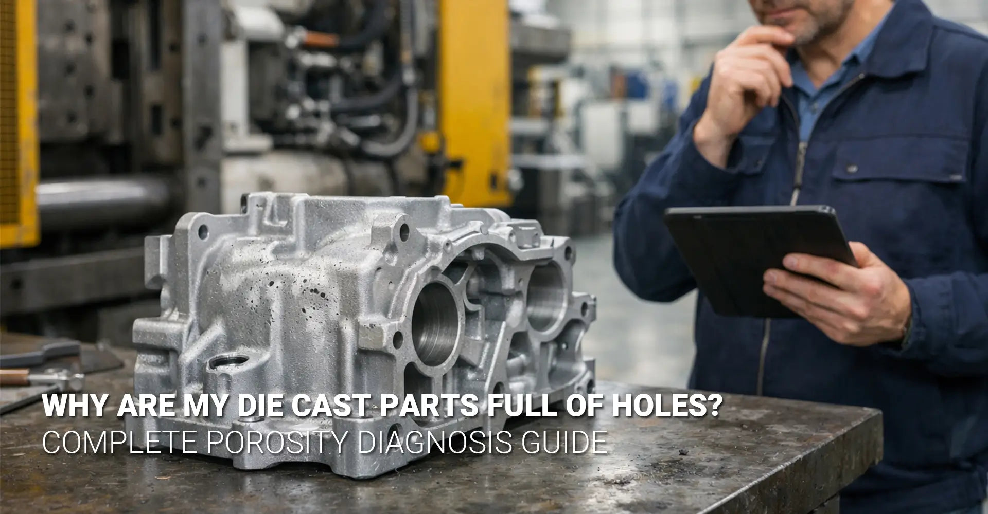
Have you ever cut open an aluminum die cast part only to discover it looks like Swiss cheese inside? This frustrating discovery affects manufacturers across industries, from automotive components to electronics manufacturing. Internal porosity represents one of the most common yet costly aluminum die casting defects that can compromise structural integrity, create leak paths, and cause catastrophic failures during pressure testing. Understanding why these holes form and how to prevent them is critical for anyone involved in metal casting production.
Quick Answer: What You Need to Know Right Now
The "Swiss Cheese" Problem Explained:
| Porosity Type | Appearance | Main Cause | Frequency |
|---|---|---|---|
| Gas porosity | Round, smooth holes | Trapped air or hydrogen | 30-60% of cases |
| Shrinkage porosity | Irregular, jagged voids | Inadequate metal feeding | 25-40% of cases |
| Outgassing porosity | Tiny scattered bubbles | Melt contamination | 10-20% of cases |
Your Action Plan:
- First, optimize runner and gate design
- Second, implement vacuum assist systems
- Third, control melt quality through degassing
- Finally, monitor process parameters continuously
While the quick answer above gives you the basics, successfully eliminating porosity requires understanding the root causes behind each defect type. Moreover, different industries demand different porosity tolerances—what works for industrial machinery may not suffice for pressure-tight automotive parts. In the following sections, we'll walk through diagnostic methods, proven solutions, and process control strategies that leading foundries use to achieve porosity rates below 1%.
Table of Contents
- What Causes the "Swiss Cheese" Effect in Die Cast Aluminum?
- How Can You Tell Gas Holes from Shrinkage Voids?
- What Runner and Gate Design Changes Stop Gas Entrapment?
- Does Vacuum Die Casting Really Control Porosity Below 1%?
- How Do Melt Quality and Degassing Prevent Hydrogen Porosity?
- What Process Parameters Should You Monitor to Prevent Porosity?
- Conclusion
What Causes the "Swiss Cheese" Effect in Die Cast Aluminum?
The term "Swiss cheese" perfectly describes what many manufacturers see when they section their aluminum castings for quality inspection. Instead of dense, solid metal, they find a network of interconnected holes that weaken the part and create potential failure points. This phenomenon doesn't happen randomly—it results from specific metallurgical and process-related issues during the die casting operation.
Three Main Culprits Behind Internal Porosity:
When molten aluminum solidifies inside a die cavity, three distinct mechanisms can create voids. First, gas porosity forms when air becomes trapped in the turbulent metal flow or when hydrogen dissolved in the melt precipitates out during cooling. Second, shrinkage porosity develops in thick sections where the metal contracts during solidification but cannot draw in additional liquid to compensate. Third, outgassing porosity occurs when contaminants in the melt release gases that form tiny bubbles throughout the casting.

Understanding the Formation Timeline:
Die casting porosity causes vary depending on when they occur in the casting cycle. Gas entrapment happens during the fill phase, typically within the first 0.05 to 0.2 seconds as molten metal rushes into the cavity at speeds up to 40 meters per second. Shrinkage develops during solidification, which takes 2 to 15 seconds depending on wall thickness. Meanwhile, outgassing can occur throughout both phases, making it particularly difficult to control. Each defect type leaves distinct signatures that trained quality inspectors can identify through careful examination.
The distribution pattern also tells a story. Gas porosity tends to concentrate along flow paths and in the last areas to fill. Shrinkage voids cluster in heavy sections and geometric hot spots where metal cools slowest. Outgassing creates a more random, dispersed pattern of fine porosity throughout the casting. Consequently, understanding these patterns helps engineers trace problems back to specific process or design weaknesses.
How Can You Tell Gas Holes from Shrinkage Voids?
Accurate die casting defect diagnosis starts with distinguishing between different porosity types because each requires different solutions. Misidentifying the problem leads to wasted time and money on ineffective countermeasures. Therefore, learning to read the visual clues becomes essential for anyone responsible for casting quality.
Visual Identification Decision Tree:
Start by examining the void shape. Round, spherical cavities with smooth walls typically indicate aluminum casting gas porosity, while irregular, dendritic shapes with rough, interconnected surfaces suggest shrinkage. Next, check the location—gas holes appear randomly distributed or along obvious flow paths, whereas shrinkage concentrates in thick sections and last-to-freeze areas. Additionally, measure the size distribution: gas porosity usually ranges from 0.1 to 3 mm in diameter, while shrinkage voids can grow much larger, sometimes exceeding 10 mm across.
| Characteristic | Gas Porosity | Shrinkage Porosity |
|---|---|---|
| Shape | Round, spherical | Irregular, jagged |
| Surface | Smooth walls | Rough, dendritic |
| Location | Flow paths, random | Thick sections, hot spots |
| Size | 0.1-3 mm typical | 1-10+ mm possible |
| Distribution | Isolated or clustered | Interconnected network |

Advanced Inspection Methods:
While visual inspection of sectioned parts provides valuable information, non-destructive testing offers deeper insights. X-ray radiography reveals the three-dimensional distribution of voids without destroying the part, making it ideal for first article inspection and production sampling. Industrial CT scanning goes further, creating detailed 3D maps that show void size, shape, and position with sub-millimeter accuracy. Furthermore, aluminum die casting void analysis using these technologies can detect defects as small as 50 microns that might escape visual detection.
For production environments, many foundries use ultrasonic testing as a faster, lower-cost alternative. However, ultrasonic methods work best for detecting larger voids and may miss fine, distributed porosity. Consequently, combining multiple inspection techniques often provides the most complete picture. Smart manufacturers establish clear acceptance criteria based on part function—pressure-tight housings demand near-zero porosity, while structural brackets may tolerate limited internal voids that don't compromise strength.
What Runner and Gate Design Changes Stop Gas Entrapment?
The gating system—runners, gates, and overflows—controls how molten metal enters the die cavity. Poor design creates turbulence that folds air into the metal stream, directly causing trapped gas in die casting. In fact, studies show that optimized gating can reduce gas porosity by 60-80% without any other process changes, making it the single most cost-effective improvement most foundries can implement.
Five Critical Design Rules for Porosity Reduction:
Rule 1: Use gradual transitions with minimum 5 mm radius curves in all runner sections. Sharp corners and abrupt direction changes create vortexes that entrain air. Similarly, avoid sudden cross-section expansions that cause flow separation.
Rule 2: Implement tangential gates that direct metal smoothly into the cavity rather than perpendicular impacts that splash and create turbulence. The entry angle should be 15-30 degrees to the cavity wall.
Rule 3: Position vents at flow termination points where air naturally collects as metal fills the cavity. Vent thickness should be 0.02-0.05 mm—thin enough to block metal but wide enough for rapid air escape.
Rule 4: Add overflow wells sized at 20-40% of the gate area to capture the initial, turbulent metal along with any oxide films and entrained gas. This "dirty" metal never enters the final part.
Rule 5: Calculate gate velocity to stay within the laminar flow range of 20-35 m/s for aluminum alloys. Slower speeds increase cycle time; faster speeds guarantee turbulence and gas entrapment.
Real-World Implementation and Results:
Die casting runner design optimization follows a systematic approach. First, use flow simulation software to predict metal velocity, turbulence intensity, and air entrapment risk before cutting steel. These tools accurately model filling patterns and highlight problem areas. Then, validate predictions with first article inspections, sectioning parts at critical locations to verify porosity levels. Subsequently, make iterative refinements based on actual results—simulation provides a starting point, but real-world validation drives final optimization.
One automotive component manufacturer reduced porosity rejection rates from 12% to under 2% by redesigning their runner system according to these principles. The changes included enlarging runner cross-sections by 30%, adding radius transitions, relocating gates from perpendicular to tangential, and increasing overflow volume. Importantly, these modifications required no new equipment or process changes—just smarter die design based on fluid dynamics principles. For manufacturers working on automotive applications where reliability is non-negotiable, such improvements deliver immediate return on investment.
Does Vacuum Die Casting Really Control Porosity Below 1%?
Vacuum die casting porosity reduction represents one of the most significant technological advances in the industry over the past two decades. By evacuating air from the die cavity before and during metal injection, vacuum systems eliminate the primary source of gas porosity. However, understanding what vacuum can and cannot do helps set realistic expectations and justify the investment.
How Vacuum Technology Changes the Game:
Traditional die casting operates at atmospheric pressure, meaning 21% of the air in the cavity is oxygen that reacts with aluminum to form oxides and gas. Additionally, this trapped air has nowhere to go during the 50-millisecond fill time except into the molten metal. Vacuum systems solve this by reducing cavity pressure to 50-200 mbar (5-20 kPa) before injection begins. Consequently, when metal enters the cavity, it encounters mostly vacuum rather than air, dramatically reducing gas entrapment.
Performance Comparison Data:
| Process Type | Typical Porosity Rate | Maximum Achievable | Best Applications |
|---|---|---|---|
| Conventional die casting | 2-5% by volume | 1-2% with optimization | Non-critical parts |
| Vacuum die casting | 0.3-1% by volume | <0.3% achievable | Pressure-tight, structural |
| Squeeze casting | <0.1% by volume | Near-zero | Aerospace, critical safety |
Implementation Considerations and ROI:
Installing vacuum capability requires either retrofitting existing machines or purchasing new vacuum-equipped systems. Retrofit costs typically range from $50,000 to $150,000 per machine depending on size and sophistication. Furthermore, cycle time increases by 1-3 seconds to allow for evacuation, reducing production throughput by 5-15%. However, for applications requiring porosity rate control under 1%, such as transmission housings, heat sinks, and structural brackets, the quality improvement justifies the investment.
Process parameters matter significantly. Vacuum level, evacuation timing, and seal integrity all affect results. Most successful operations target 50-100 mbar vacuum for aluminum alloys, initiated 0.5-1.0 seconds before shot start. Additionally, they maintain vacuum throughout fill and initial solidification, using special seals that withstand repeated thermal cycles. Regular maintenance of vacuum pumps and seals ensures consistent performance—degraded seals allow air infiltration that defeats the purpose of the system.
Interestingly, vacuum primarily addresses gas porosity but has limited effect on shrinkage porosity, which forms due to inadequate feeding during solidification. Therefore, achieving total porosity under 1% requires combining vacuum technology with proper thermal management and gating design. This integrated approach delivers the best results for demanding applications in industrial machinery and other sectors.
How Do Melt Quality and Degassing Prevent Hydrogen Porosity?
While turbulence-related gas porosity gets most of the attention, hydrogen dissolved in molten aluminum creates its own unique challenges. Hydrogen is the only gas significantly soluble in liquid aluminum, and its solubility drops dramatically during solidification. This forces hydrogen out of solution, forming countless tiny, round pores throughout the casting. Understanding and controlling melt chemistry therefore becomes critical for eliminating this subtle but pervasive defect.
The Hydrogen Problem Explained:
Aluminum absorbs hydrogen from moisture in the air, wet tools, damp charge materials, and chemical reactions with lubricants or release agents. At casting temperature (680-720°C), aluminum can dissolve up to 0.7 mL of hydrogen per 100g of metal. However, upon solidification, that capacity drops to just 0.05 mL/100g. Consequently, the excess hydrogen precipitates as gas bubbles that become frozen into the microstructure. Even small amounts—just 0.3 mL/100g—can create objectionable porosity levels.
Melt Treatment Best Practices Checklist:
✓ Use dry charge materials stored in climate-controlled areas with relative humidity below 50%
✓ Preheat all tools and ladles to at least 200°C to drive off moisture before contacting molten metal
✓ Implement rotary degassing with nitrogen or argon for 5-10 minutes, achieving hydrogen levels below 0.15 mL/100g
✓ Monitor melt temperature precisely—overheating increases hydrogen pickup exponentially
✓ Test hydrogen content using reduced pressure testing (RPT) or Alscan analyzers before each production run
✓ Control furnace atmosphere to minimize water vapor and combustion gases contacting the melt surface
Alloy-Specific Considerations:
Different aluminum alloys exhibit varying susceptibility to hydrogen porosity. Silicon-rich alloys like A380 and A383, commonly used in die casting, have relatively good resistance due to their wide solidification range that allows time for hydrogen to escape. Conversely, higher-purity alloys with narrow freezing ranges trap hydrogen more readily. Additionally, alloys containing magnesium above 0.3% tend to form oxide films that interfere with degassing effectiveness, requiring longer treatment times or higher gas flow rates.
Degassing efficiency verification should occur regularly—ideally before each shift. The reduced pressure test provides a simple, reliable method: pour a small sample into a cup, solidify it under partial vacuum, then measure the density difference between the vacuum sample and a normally solidified sample. Density reduction above 1% indicates excessive hydrogen that will likely cause porosity in production castings. Subsequently, additional degassing treatment can correct the problem before casting begins, preventing scrap rather than discovering it during inspection.
For manufacturers focused on achieving excellent surface finish quality, controlling hydrogen porosity becomes especially important because subsurface voids often break through during machining or finishing operations, creating cosmetic defects that require rework or scrapping.
What Process Parameters Should You Monitor to Prevent Porosity?
Even with optimized die design, vacuum systems, and clean melt, process variability can still cause porosity issues. Therefore, establishing robust process monitoring and statistical control ensures consistent quality over thousands of cycles. The key lies in identifying which parameters truly predict porosity risk and setting appropriate control limits based on capability studies.
Critical Parameter Control Windows:
Modern die casting machines generate dozens of data points every cycle, but only a handful critically influence porosity formation. Focus monitoring efforts on these high-impact variables:
| Parameter | Control Range | Impact on Porosity | Monitoring Method |
|---|---|---|---|
| Fill speed | 20-35 m/s | Direct—higher = more turbulence | Shot curve analysis |
| Vacuum level | 50-100 mbar | Direct—lower = less gas entrapment | Continuous vacuum sensor |
| Die temperature | ±15°C of setpoint | Indirect—affects shrinkage | Thermal imaging |
| Injection pressure | 40-80 MPa | Indirect—affects density | Hydraulic pressure sensor |
| Cycle time | ±2 seconds of target | Indirect—affects thermal balance | Timer |
First Article Inspection Protocol:
Before starting production runs, thorough first article validation prevents costly mistakes. Section at least three parts from different cavity positions (if multi-cavity dies), examining wall sections, junctions, and thick areas where porosity typically concentrates. Measure total porosity percentage using image analysis software on polished cross-sections. Additionally, verify that individual void sizes stay below acceptance criteria—typically 0.5 mm maximum for structural parts, 0.2 mm for pressure-tight applications.
Statistical Process Control Implementation:
Once baseline capability is established, implement SPC charts for key parameters. X-bar and R charts track parameter means and variation, triggering alerts when trends approach control limits. For porosity itself, use automated X-ray inspection on a statistical sample—typically 5% of production or one part per hour, whichever is more frequent. Plot porosity percentages on individual and moving range (I-MR) charts to detect shifts before they cause widespread quality issues.
Advanced facilities employ machine learning algorithms that correlate multiple parameters simultaneously, predicting porosity risk for each cycle. When the algorithm detects high-risk combinations—such as slightly low vacuum combined with above-average fill speed—the system can automatically adjust parameters or flag the part for 100% inspection. This predictive approach prevents defects rather than merely catching them after formation.
For electronics manufacturing applications where thin walls and complex geometries challenge traditional process control, such advanced monitoring becomes particularly valuable. The combination of tight parameter control and statistical validation creates the foundation for achieving and maintaining porosity levels below 1% consistently.
Conclusion
Eliminating the "Swiss cheese" effect in aluminum die castings requires a systematic, multi-faceted approach rather than any single silver bullet solution. As we've explored, successful porosity control begins with accurate diagnosis—understanding whether you're fighting gas entrapment, shrinkage, or hydrogen-related defects. From there, the solution path becomes clear: optimize your gating system to promote laminar flow, implement vacuum assist for demanding applications, maintain excellent melt quality through rigorous degassing, and establish robust process monitoring to ensure consistency.
The good news is that modern die casting technology, when properly applied, can routinely achieve porosity levels below 1% even for complex geometries and challenging alloys. However, this performance doesn't happen by accident—it requires engineering discipline, quality systems, and ongoing attention to process fundamentals. Whether you're producing components for automotive powertrains, industrial equipment, or consumer electronics, investing in porosity reduction delivers tangible returns through lower scrap rates, improved part performance, and enhanced customer satisfaction.
Your next steps should prioritize the highest-impact improvements first. Start by reviewing your current gating design using the principles outlined in section three. Then evaluate whether vacuum die casting makes economic sense for your application mix. Finally, establish the process monitoring framework described in section six to maintain the gains you achieve. Remember that porosity control is a journey of continuous improvement, not a destination—the best foundries never stop refining their understanding and capabilities.
Recommended Resources
[Aluminum die casting defects][^1]
[die casting porosity causes][^2]
[aluminum casting gas porosity][^3]
[die casting runner design optimization][^4]
[porosity rate control under 1%][^5]
[die casting defect diagnosis][^6]
----
[^1]: A professional technical guide categorizing major aluminum die casting defects such as cold shuts, flashes, and blisters, with detailed root-cause analysis and preventative measures for each stage of the high-pressure die casting process.
[^2]: An in-depth engineering analysis focusing specifically on the nine critical causes of shrinkage and gas porosity in die casting, covering variables like gate design, intensification pressure, and thermal hotspots in the mold
[^3]: A peer-reviewed scientific study published in the PMC database that investigates the mechanisms of hydrogen dissolution in molten aluminum, detailing the chemical relationship between solid fraction increases and the rapid development of gas porosity bubbles.
[^4]: An engineering research study demonstrating the transition from fan-type to tangential runner designs using CFD (Computational Fluid Dynamics) simulation to achieve smooth metal flow, reduce mold erosion, and minimize porosity through precise runner trajectory analysis.
[^5]: An industry-leading technical article from Shibaura Machine (formerly Toshiba Machine) explaining how advanced shot control and real-time intensification pressure monitoring allow manufacturers to compress internal gas voids and achieve volumetric porosity rates significantly below the 1% threshold required for high-liability parts.
[^6]: A professional engineering guide that provides a systematic framework for diagnosing die casting failures, including the use of X-ray/CT inspection, NADCA standards for surface quality, and design-led solutions to eliminate recurring defects like cold shuts, flashes, and sink marks.


