How Does Balanced Turning Increase CNC Lathe Productivity by 80%?
How Does Balanced Turning Increase CNC Lathe Productivity by 80%?

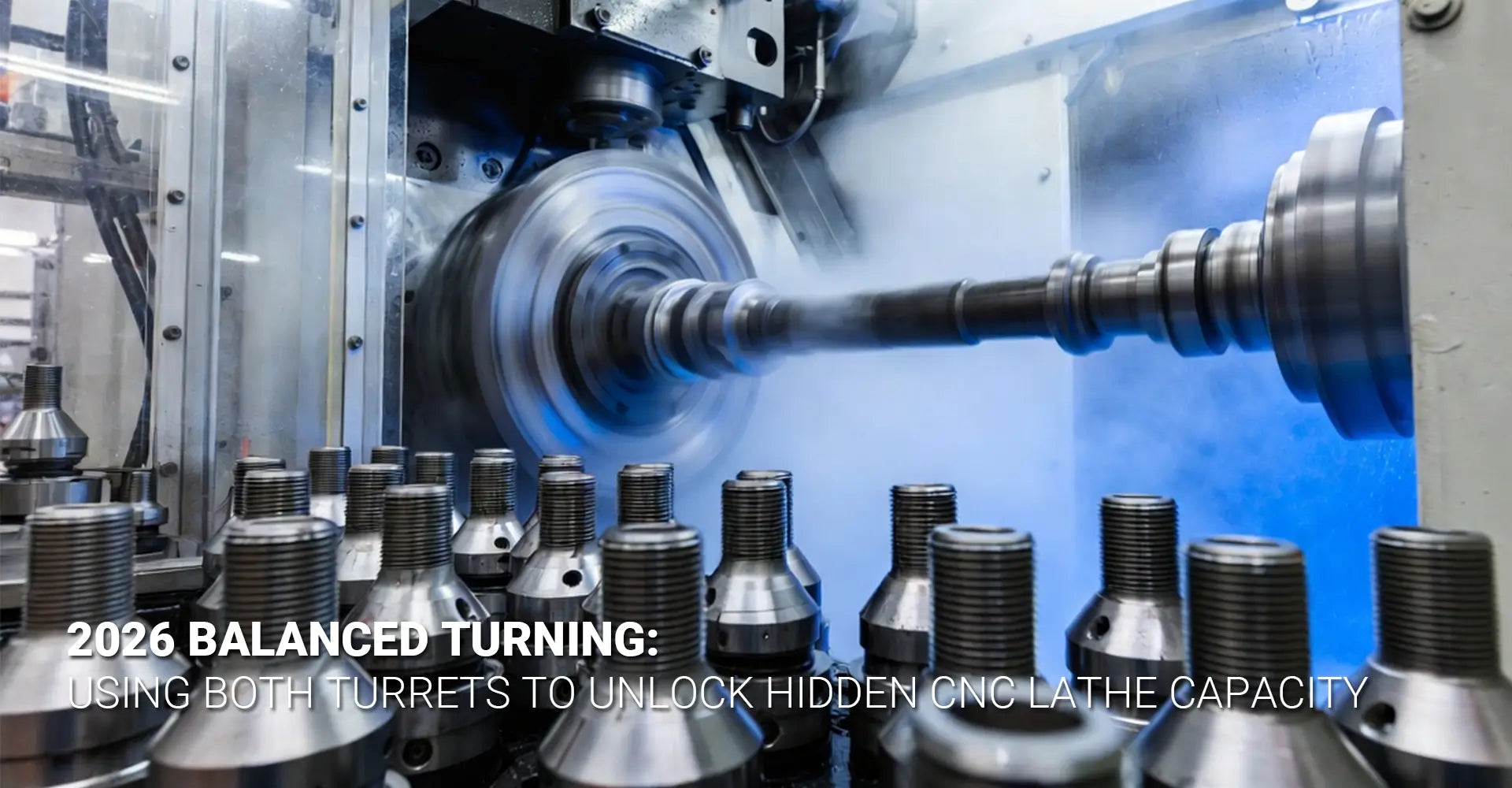
Most machine shops invest in twin-turret CNC lathes expecting double the capability, yet they leave one turret idle during production runs. This single oversight costs manufacturers thousands of hours in lost productivity every year. Balanced turning changes that equation completely by putting both turrets to work simultaneously, unlocking hidden capacity that's already sitting on your shop floor.
Quick Answer: What You Need to Know About Balanced Turning
What it is: Balanced turning uses both turrets simultaneously to cut from opposite sides of a rotating workpiece
Key benefit: 80% faster roughing without adding machine hours or buying new equipment
Best for: Long shafts, slender parts prone to deflection, and high-volume production runs
Requirements: Twin-turret lathe + synchronized programming + proper workholding
This technique transforms how you approach CNC turning operations, especially for parts that have traditionally been difficult to machine efficiently.
If you're ready to stop leaving productivity on the table and start using the full capacity of your existing equipment, this guide will walk you through everything you need to know. Moreover, we'll cover the mechanics, the benefits, the challenges, and the practical steps to implement balanced turning in your shop.
Table of Contents
- Why Do Most Shops Use Only One Turret on Twin-Turret Lathes?
- What Is Balanced Turning and How Does It Work?
- How Does Simultaneous Roughing Reduce Cycle Time Without Extra Hours?
- How Can You Control Deflection on Long Shafts Using Balanced Turning?
- Conclusion
Why Do Most Shops Use Only One Turret on Twin-Turret Lathes?
Walk into most machine shops and you'll notice something strange: expensive twin-turret lathes running with only one turret engaged. The second turret sits idle, doing nothing while the active tool makes slow, careful cuts. This scenario plays out thousands of times every day across manufacturing facilities worldwide.
Three Main Reasons Shops Ignore the Second Turret:
- Programming complexity – Synchronized toolpaths require additional training and CAM expertise
- Fear of collisions – Shop managers worry about crashes when two tools move simultaneously
- "It works fine" mindset – Single-turret operations meet current production schedules, so there's no urgency to change

The reality runs deeper than these surface-level concerns. Many programmers learned CNC on single-turret machines and simply never received training on dual-turret operations. Additionally, CAM software defaults often favor single-tool strategies because they're easier to verify and less likely to generate alarm conditions.
Furthermore, some shops purchased twin-turret machines specifically for tool redundancy or quick changeovers, not realizing the CNC turning productivity gains available through simultaneous engagement. The training gap persists because most technical schools still teach traditional single-tool methods, leaving the next generation of machinists unaware of balanced turning capabilities.
Risk aversion plays a significant role as well. A single collision between two synchronized tools can cause expensive damage and downtime. Therefore, without proper simulation tools and clear safe-zone programming, many shops choose the conservative path of using one turret at a time. This caution makes sense in the short term but costs significantly more in the long run through lost capacity and slower cycle times.
What Is Balanced Turning and How Does It Work?
Balanced turning represents a fundamental shift in how CNC lathes remove material. Instead of relying on a single cutting edge to peel away metal, this technique engages two tools simultaneously from opposite sides of the rotating workpiece. The result is a dramatic increase in material removal rates without proportional increases in cycle time.
Core Mechanics in Plain Language:
The primary turret positions a cutting tool on one side of the part while the secondary turret positions another tool directly opposite. Both tools advance at synchronized feed rates, cutting equal depths from opposing sides. Consequently, the radial cutting forces cancel each other out instead of pushing the workpiece away from the tool.
The synchronization happens at the control level, where the CNC program coordinates both toolpaths to maintain precise positioning throughout the cut. Think of it like two people pushing a door from opposite sides with equal force—the door stays centered instead of swinging wildly in one direction.
Balanced turning on CNC lathes requires careful attention to several technical factors. First, both tools must engage the workpiece at nearly identical moments to prevent sudden shock loads. Second, the depth of cut and feed rates need to match precisely so neither tool becomes overloaded. Third, the toolpaths must maintain safe clearance zones to prevent collisions during rapid positioning moves.
The technique works particularly well with symmetrical roughing operations on cylindrical parts. For instance, when turning down a 2-inch diameter shaft to 1.5 inches, a balanced turning approach allows both tools to remove 0.25 inches of material simultaneously rather than requiring one tool to remove the full 0.5 inches in sequence.
Radial force balance in CNC turning explains why this method works so effectively on problematic parts. When a single tool cuts into a rotating workpiece, it generates radial force that pushes the part away from the cutting edge. On rigid, short parts this deflection might be negligible. However, on long, slender shafts, this deflection causes taper, vibration, and poor surface finish. By cutting from opposite sides simultaneously, the forces balance out and the workpiece stays centered in the spindle.
Modern CNC controls make synchronization relatively straightforward through features like coordinated axis motion and master-slave programming relationships. Nevertheless, the programmer must still define safe approach paths, engagement sequences, and emergency stop protocols to ensure collision-free operation throughout the entire cycle.
How Does Simultaneous Roughing Reduce Cycle Time Without Extra Hours?
The mathematics of simultaneous roughing with two tools reveals why productivity jumps so dramatically. In traditional single-tool roughing, the cutting tool must make multiple passes to reduce the workpiece diameter to the desired size. Each pass removes a limited amount of material based on what the tool can safely handle without deflection or premature wear.
Material Removal Rate Comparison:
| Method | Tools Engaged | Depth Per Pass | Total Passes | Relative Speed |
|---|---|---|---|---|
| Single Tool | 1 | 0.100" | 5 passes | Baseline (1x) |
| Balanced Turning | 2 | 0.100" each | 3 passes | 1.8x faster |
The speed increase doesn't come from running the machine faster—it comes from doing more work per revolution of the spindle. When both tools cut simultaneously, each revolution removes roughly twice the volume of material compared to single-tool operation. As a result, the part reaches finish dimensions in significantly fewer passes.
Twin turret CNC turning productivity gains extend beyond just faster material removal. Because each tool handles half the total cutting load, both tools experience less stress and heat buildup. This load sharing often extends tool life by 30-50% compared to single-tool operations at equivalent removal rates.
Additionally, the balanced force distribution allows programmers to push feed rates higher without risking deflection-related quality issues. On a typical shaft turning operation, this might mean increasing from 0.012 inches per revolution to 0.016 inches per revolution—a 33% boost in linear material removal speed on top of the doubled engagement.
Consider a practical example from automotive manufacturing: turning a 20-inch-long drive shaft from 3.0 inches diameter to 2.5 inches diameter. With traditional single-tool roughing at 0.125-inch depth of cut, this requires two complete roughing passes taking approximately 8 minutes of cycle time. Using balanced turning with the same depth of cut per tool, the operation completes in roughly 4.5 minutes—a time savings that compounds across hundreds of parts per shift.
The productivity gains become even more impressive when considering that these improvements require no additional capital investment beyond the machine you already own. Therefore, implementing balanced turning represents one of the highest-ROI process improvements available in CNC machining service operations.
Furthermore, roughing productivity without extra cycle time becomes achievable because the two tools work in parallel rather than in sequence. The machine isn't running longer—it's simply accomplishing more during the same spindle rotations. This parallel processing advantage mirrors how multi-core processors revolutionized computing by doing multiple tasks simultaneously rather than faster sequential processing.
Tool life extension adds another layer of productivity benefit. When tools last longer between changes, machines spend less time in setup and more time cutting. On high-volume production runs, this can translate to several additional productive hours per shift simply from reduced tool change frequency.
How Can You Control Deflection on Long Shafts Using Balanced Turning?
Long, slender shafts represent one of the most challenging workpieces in turning operations. The problem stems from basic physics: when a cutting tool applies force to a long, thin workpiece, the part bends away from the cutting edge like a fishing rod under load. This deflection causes dimensional errors, taper, chatter marks, and sometimes complete part rejection.
Why Single-Tool Cuts Cause Bending and Chatter:
When a single tool engages a long shaft, it creates an unbalanced radial force vector pushing the workpiece away from the cutting edge. The longer and thinner the shaft, the more pronounced this deflection becomes. Even with a steady rest or tailstock support, the cutting forces can cause vibration that manifests as chatter marks on the finished surface.
Reducing deflection on long shafts turning becomes dramatically easier with balanced turning because the opposing tools create equal and opposite force vectors. Instead of pushing the shaft in one direction, the forces cancel out and the workpiece remains centered on its rotational axis. This force balance allows much more aggressive cutting parameters on parts that would otherwise require conservative feeds and speeds.
The mechanics work similarly to how airplane wings generate lift through pressure differential. In balanced turning, however, instead of creating lift, the opposing pressures keep the workpiece stable. When the top tool pushes down with 200 pounds of force, the bottom tool simultaneously pushes up with 200 pounds of force, resulting in near-zero net deflection.
Long slender shaft chatter control improves dramatically because balanced cutting eliminates the primary source of vibration—the unbalanced radial force that excites the workpiece's natural resonant frequency. Chatter occurs when cutting forces cause the workpiece to vibrate at frequencies that feedback into the cutting process, creating a self-reinforcing oscillation. By neutralizing the radial forces, balanced turning breaks this feedback loop before it starts.
Support strategies become even more effective when combined with balanced cutting. A tailstock or steady rest that might only partially stabilize a shaft under single-tool cutting can provide complete rigidity when radial forces are balanced. Moreover, the combination allows you to machine parts that would be nearly impossible with conventional methods.
For example, turning a shaft with a length-to-diameter ratio of 20:1 (a 20-inch shaft that's 1 inch in diameter) presents extreme deflection challenges with single-tool methods. Even with excellent workholding, such parts tend to bow, vibrate, and produce poor surface finishes. With balanced turning and proper support, these same parts can be machined to tight tolerances with excellent surface quality.
The technique proves particularly valuable in industrial machinery applications where long precision shafts are common. Pump shafts, transmission components, and hydraulic rams all benefit from the deflection control that balanced turning provides.
Dual toolholder synchronized turning also enables the use of different tool geometries on each turret to manage specific challenges. For instance, one tool might use a sharp cutting edge for excellent finish while the opposing tool uses a stronger, more robust edge geometry for stability. This asymmetric approach still provides most of the deflection control benefits while optimizing for surface finish or tool life.
Additionally, balanced turning allows you to work with CNC metals plastics materials that might be too flexible for conventional single-tool methods. Certain plastics and aluminum alloys that deflect easily under cutting forces become much more machinable when radial forces are balanced.
The quality improvements extend beyond just dimensional accuracy. Surface finish typically improves by 20-40% when deflection is eliminated, reducing or eliminating secondary finishing operations. Parts come off the machine ready for assembly rather than requiring additional grinding or polishing steps.
Conclusion
Improve roughing rates on CNC lathe operations by implementing balanced turning, and you'll unlock productivity that's been hiding in plain sight on your shop floor. The 80% speed increase isn't marketing hype—it's a mathematical certainty when you double the number of cutting edges engaged in material removal while maintaining the same cutting parameters.
CNC turning cycle time reduction happens immediately once you program and verify your first balanced turning operation. The technique requires no additional capital equipment beyond what most shops already own, making it one of the most cost-effective process improvements available in manufacturing today.
The key takeaways for successful implementation include:
- Start with simple cylindrical parts to build confidence and verify programming methods
- Invest in simulation software to validate toolpaths before cutting metal
- Train both programmers and operators on synchronized toolpath strategies
- Begin with conservative parameters and gradually increase aggressiveness as experience grows
- Focus initial efforts on long, slender parts where deflection control provides maximum benefit
The ROI potential is substantial. A single twin-turret lathe running balanced turning instead of single-tool operations can effectively gain the productive capacity of a second machine without the capital investment. Over a year, this translates to thousands of additional billable machine hours from equipment you've already purchased.
Your first steps should include reviewing your current job mix to identify parts that would benefit most from balanced turning. Long shafts, high-volume production runs, and parts currently experiencing deflection problems represent ideal candidates. Additionally, consider partnering with your custom CNC milling services provider to develop programming standards and best practices.
The shops that master balanced turning gain a significant competitive advantage in bidding and delivery times. While competitors struggle with deflection issues and slow cycle times, you'll be delivering higher-quality parts faster and at lower cost per piece. That's the kind of capability that wins new business and builds long-term customer relationships.
Recommended Resources
-----
[^1]. This comprehensive guide explores best practices for maximizing efficiency in CNC turning, covering toolpath optimization, tooling selection, and the integration of precision milling to reduce cycle times and improve overall throughput.
[^2]. This technical article explains the principles of balanced cutting on CNC lathes, demonstrating how simultaneously machining with two turrets cancels out cutting forces to reduce vibrations, increase feed rates, and improve stability for slender workpieces.
[^3]. This technical blog compares single and twin turret CNC turning centers, highlighting how dual turret configurations maximize productivity by allowing simultaneous machining at different positions, which drastically shortens production cycles for complex parts.


