Broke a Tap in a $500 Part? Why CNC Thread Milling Should Be Your New Standard in 2026?
Broke a Tap in a $500 Part? Why CNC Thread Milling Should Be Your New Standard in 2026?

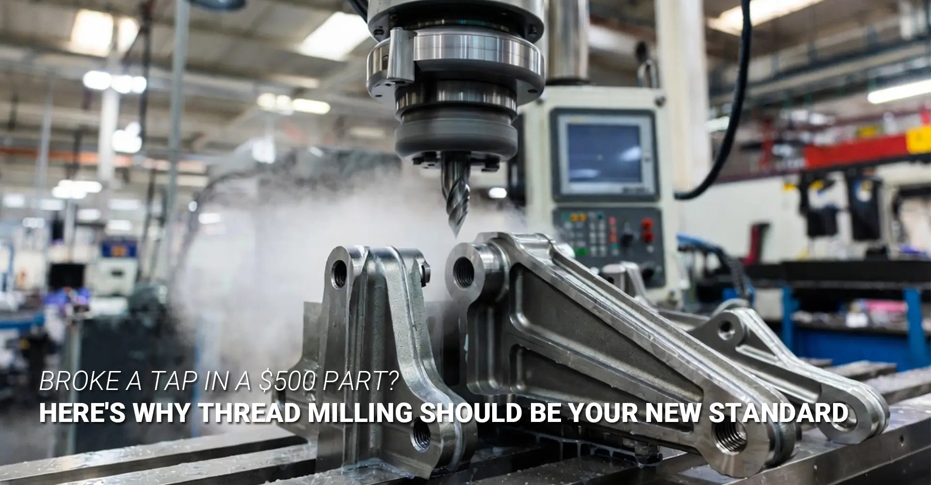
You've just spent 20 hours machining a complex aerospace bracket. The material is 4140 steel. Every feature is perfect. Then comes the final operation — threading. You hear a crack. The tap is gone. Buried in the hole. And so is your part.
This isn't a rare horror story. It happens every day in machine shops around the world. And it's almost always 100% preventable.
Here's the short answer: CNC thread milling is a threading method where a rotating cutter follows a helical path through X, Y, and Z axes simultaneously to cut threads. Unlike tapping, it uses light cutting engagement — around 5% — which means lower forces, better chip control, and most importantly, if the tool breaks, your part survives.
So if you're still running taps on complex, high-value parts, this article is for you. We'll walk through exactly why thread milling works better, how it compares to tapping head-to-head, and how to get started today. Let's get into it.
Table of Contents
- The Nightmare Scenario — When a Broken Tap Ruins Your Final Operation?
- What Is CNC Thread Milling, and How Does It Actually Work?
- Thread Milling vs. Tapping — Head-to-Head Comparison for 2026 Machining?
- Practical Setup — How to Get Started with Thread Milling on Your CNC?
- Conclusion & 2026 Threading Decision Checklist
The Nightmare Scenario — When a Broken Tap Ruins Your Final Operation?
Picture this. You're on the last step of machining a part that took the better part of a full shift to complete. The geometry is complex. The tolerances are tight. The material fought back the whole time. But you made it. Now it's time to thread a blind hole — and then the tap snaps.
That single moment wipes out everything. The hours. The material cost. The setup time. And in many cases, the customer deadline too. This is the exact scenario that gets posted on r/CNC almost weekly, and it's the kind of loss that sticks with machinists for a long time.
Key Fact: A broken tap in a blind hole almost always results in a scrapped workpiece. Unlike a broken end mill, a tap's flutes are fully engaged in the material — making extraction nearly impossible without damaging the threads or the part itself.

So why does this keep happening? There are three main reasons taps fail — especially in complex parts.
First, chip clogging. In a blind hole, chips have nowhere to go. They pack into the flutes, torque spikes, and the tap twists apart. This is especially brutal in ductile materials like stainless steel or aluminum.
Second, torque spikes. Tapping engages nearly the entire thread form at once — that's 90%+ contact. Any variation in material hardness, chip load, or coolant delivery can cause a sudden torque spike that snaps the tool instantly.
Third, the blind hole depth trap. Machinists sometimes push taps close to the bottom of a blind hole to maximize thread engagement. This leaves almost zero room for chip evacuation or torque relief — and the tap pays the price.
The frustrating part? Tap breakage prevention starts with choosing the right process — not just the right tap. And that's exactly where thread milling changes the game.
What Is CNC Thread Milling, and How Does It Actually Work?
Most machinists learn tapping first. It's fast, simple, and gets the job done in the right conditions. But thread milling is a fundamentally different approach — and once you understand how it works, the advantages become obvious.
Instead of a tool that screws itself into the hole, a thread mill cutter rotates on its own axis while simultaneously moving in a helical path through the hole. The CNC machine controls X, Y, and Z movement at the same time. The result? A precisely cut thread formed with minimal contact and force.
Quick Definition: Thread milling = a rotating cutter following a programmed helical path in X, Y, and Z simultaneously to form threads — using around 5% cutting engagement compared to tapping's 90%+.
This helical motion is called helical interpolation CNC — and it's the technical foundation that makes thread milling work. Most modern 3-axis CNC mills already support this. You don't need rigid tapping, special spindle synchronization, or any exotic machine capability. If your machine can run circular interpolation in X and Y while moving in Z, you're ready.
Now, here's where tool selection matters. There are two main cutter types:
Single-point thread mill — Also called a single-form cutter. It has one thread-form profile ground into the tool. Because the thread is created entirely by the toolpath rather than the tool geometry, one cutter can produce a wide range of thread diameters and pitches. It can even cut right-hand and left-hand threads. This is the most flexible option — ideal for job shops with many different thread sizes.
Multi-form thread mill — This cutter has multiple thread profiles stacked along its length. It cuts faster because it covers more of the thread in a single pass. However, it's locked to one specific thread pitch and diameter range. Best for high-volume production of a single thread specification.
Choosing between them comes down to one question: are you running high-volume identical threads, or do you need flexibility across many part numbers? For most job shops and contract manufacturers handling custom CNC milling services, the single-form cutter wins for its versatility.
Thread Milling vs. Tapping — Head-to-Head Comparison for 2026 Machining?
This is the section most machinists actually need. Not theory — a direct comparison. Here's how the two methods stack up across the factors that matter most in real production.
When evaluating thread milling vs tapping, one thing becomes clear immediately: tapping wins on raw speed for simple holes in easy materials. But speed is rarely the only variable that matters.
Quick Comparison Table
| Factor | Tapping | CNC Thread Milling |
|---|---|---|
| Blind Hole Chip Control | Poor | Excellent |
| Broken Tool = Scrap? | Usually Yes | Usually No |
| One Tool, Multiple Sizes | No | Yes (single-form) |
| Cutting Engagement | ~90%+ | ~5% |
| Cycle Time per Hole | Faster | Slightly Slower |
| Hard Material Performance | Risky | Reliable |
| Left & Right Hand Threads | Separate taps needed | Same cutter, different path |
| Thread Quality | Good | Excellent |
Let's break down the four factors that matter most.
Blind hole threading — chip control is everything. Tapping in a blind hole is essentially forcing chips into a dead end. They pack, pressure builds, and the tap breaks. Internal thread milling, on the other hand, produces small comma-shaped chips that evacuate easily — especially with a directed air blast or through-spindle coolant. This single difference makes thread milling the correct choice for the majority of blind hole applications, particularly in tough alloys.
Tool breakage consequences — this is the big one. When a tap breaks, its flutes are locked into the material. Extraction means EDM, broken tap extractors, or scrapping the part. When a thread mill breaks, it's following a helical path with light contact. The broken piece can be withdrawn from the hole. A new cutter picks up where it left off. The part survives. This is the difference between a tool change and a scrapped part.
Size flexibility — one cutter, many threads. With tapping, every thread size and pitch needs its own tap. Switch from M8x1.25 to M8x1.0? New tap. Need a left-hand thread? Another tap. A single-point thread mill eliminates this entirely. One cutter handles a wide range of diameters. This reduces tooling inventory, tool change time, and the mental overhead of managing dozens of taps. For shops running CNC machining services across varied part families, this flexibility has real value.
Cutting forces — 5% vs. 90%+ engagement. This difference matters most in thin-wall parts, delicate features, and hard materials. Tapping applies massive radial force to the workpiece. Thread milling applies force gradually, from one direction at a time. In titanium, Inconel, and hardened steels — materials increasingly common in industrial machinery and aerospace components — this low-force approach is often the only reliable path to a good thread.
Practical Setup — How to Get Started with Thread Milling on Your CNC?
Understanding the advantages is one thing. Actually running thread milling in your shop is another. Here's what you need, and what to do first.
Getting started with thread milling is more straightforward than most machinists expect. The biggest barrier is usually programming — but with modern CAM software and manufacturer-supplied G-code templates, that hurdle is lower than ever.
Quick-Start Checklist
- ✅ Machine capable of helical interpolation (simultaneous X, Y, Z movement)
- ✅ Proper toolholding — Weldon shank or set-screw holder recommended
- ✅ Correct speeds & feeds per material (start conservative, adjust from data)
- ✅ CAM software with helical interpolation support, or manufacturer G-code
- ✅ Chip evacuation plan — air blast, flood coolant, or through-spindle coolant
Programming — thread milling G-code basics. The core move in thread milling is a helical arc. In most CNC controls, this is written using G02 or G03 (circular interpolation) combined with a Z-axis move in the same block. The result is a single helical pass that cuts the thread. Here's the basic logic:
- Move to hole center at a safe Z height
- Plunge to thread depth
- Execute helical arc (one full 360° turn per pitch) while moving in Z
- Return to center and retract
Most CAM packages (Fusion 360, Mastercam, Hypermill) have dedicated thread milling cycles that handle this automatically. If you're writing manually, your thread mill manufacturer will typically supply tested G-code examples — use them.
Toolholding matters more than you think. Thread mills generate side loads during the helical move. A tool that pulls out or shifts mid-cut will destroy thread quality. Weldon shank holders with a set-screw bearing directly on the flat are the most common recommendation. Hydraulic chucks also work well for vibration damping. Avoid relying solely on friction-grip collets for thread milling — especially in tougher materials.
Speeds and feeds — starting points by material. These are conservative starting points. Adjust based on your machine, your tool manufacturer's data, and your specific alloy:
| Material | Surface Footage (SFM) | Notes |
|---|---|---|
| Aluminum | 400–600 SFM | Dry or air blast preferred |
| Mild Steel | 150–250 SFM | Flood coolant recommended |
| Stainless Steel | 80–150 SFM | Coolant critical — reduces work hardening |
| 4140 / Tool Steel | 100–180 SFM | Climb milling preferred |
| Titanium | 50–100 SFM | Low feeds, high coolant pressure |
| Inconel | 30–60 SFM | Carbide grade selection critical |
Coolant strategy. For aluminum and general steel, dry machining with air blast often works well. For stainless — where work hardening is a real risk — coolant is strongly recommended. For deep blind holes in any material, through-spindle coolant or a directed air blast is the best way to ensure chip evacuation. This is the same principle that makes thread milling so reliable in the CNC turning of threaded features on turned parts with live tooling.
One more note for shops serving the automotive sector: thread milling is increasingly specified for powertrain and structural components in aluminum and high-strength steel. The combination of thread quality, process reliability, and the ability to hold tight tolerances across production runs makes it a natural fit for parts where thread failure has serious consequences.
Conclusion And Your 2026 Threading Decision Checklist
Tapping is not going away. For simple, through-holes in easy materials at high volume, it remains fast and cost-effective. But the moment complexity enters the picture — blind holes, tough alloys, thin walls, high-value parts — tapping becomes a liability.
Thread milling advantages come down to three things: the tool can break without scrapping the part, chip control is manageable in the worst-case geometries, and one cutter handles more than one job. Those three things add up to real money saved and real stress avoided.
Here's your 2026 Threading Decision Checklist — use this before your next job:
Choose Thread Milling when:
- ✅ The part is high-value and cannot be scrapped
- ✅ You're threading blind holes, especially in tough materials
- ✅ The material is stainless, titanium, Inconel, or hardened steel
- ✅ You need multiple thread sizes from one tool
- ✅ Thin walls or delicate features are involved
- ✅ Left-hand threads are required
- ✅ Thread quality and surface finish are critical
Tapping may still be appropriate when:
- ✅ Through-holes in aluminum or mild steel
- ✅ High-volume production of one thread size
- ✅ Cycle time is the primary constraint
- ✅ The part is low-cost and replacement is acceptable
If your shop regularly handles complex, precision work — the kind that demands reliability over raw speed — thread milling deserves a permanent place in your process. The tools are accessible, the programming is learnable, and the protection it gives your parts is immediate.
External Links Recommendation
[CNC thread milling][^1]
[thread milling vs tapping][^2]
[thread mill cutter][^3]
[helical interpolation CNC][^4]
[internal thread milling][^5]
[blind hole threading][^6]
[^1]. A comprehensive technical guide to CNC thread milling, covering key parameters like pitch and spindle speed, various cutter types, and best practices for achieving high-precision internal and external threads in manufacturing.
[^2]. An in-depth comparison between thread milling and tapping, detailing the operational differences, advantages, and disadvantages of each method to help machinists choose the most efficient threading process for their specific applications.
[^3]. A detailed guide to understanding thread mill cutters, covering essential considerations such as tool geometry, cutter diameter selection, and strategies for successful radial passes and chip evacuation in CNC machining.
[^4]. An expert resource explaining helical interpolation in CNC programming, focusing on its applications in thread milling, hole creation, and spiral ramping, including practical G-code examples and feed/speed optimization tips.
[^5]. A professional technical guide from Sandvik Coromant providing expert application tips for internal thread milling, including tool path optimization, choice of cutting diameter, and best practices for achieving high-quality thread profiles.
[^6]. An in-depth resource exploring the challenges and solutions for blind hole threading, offering essential tips on chip evacuation, maximum tapping depth calculations, and tool selection to prevent tap breakage in CNC machining.
1 comment


This is a lifesaver of an article—I recently lost a high-value titanium aerospace part to a snapped M6 tap, and I’m definitely making the switch to thread milling for our 2026 projects. I was actually just listening to a technical segment about tool longevity and they mentioned the Newsens application for reducing friction in high-heat cycles, which you can hear about here https://podcast.kkbox.com/sg/episode/Kl41jNQd-KTbLZv8zL , but I’m curious: if I’m using a single-point mill on hardened 4140, would this specific coating or a similar additive provide a noticeable benefit over standard flood coolant, or is the 5% engagement enough to manage the heat on its own?