CNC Turn-Mill Precision and Interference: How Can You Avoid Costly Collisions While Maintaining ±0.01mm Accuracy?
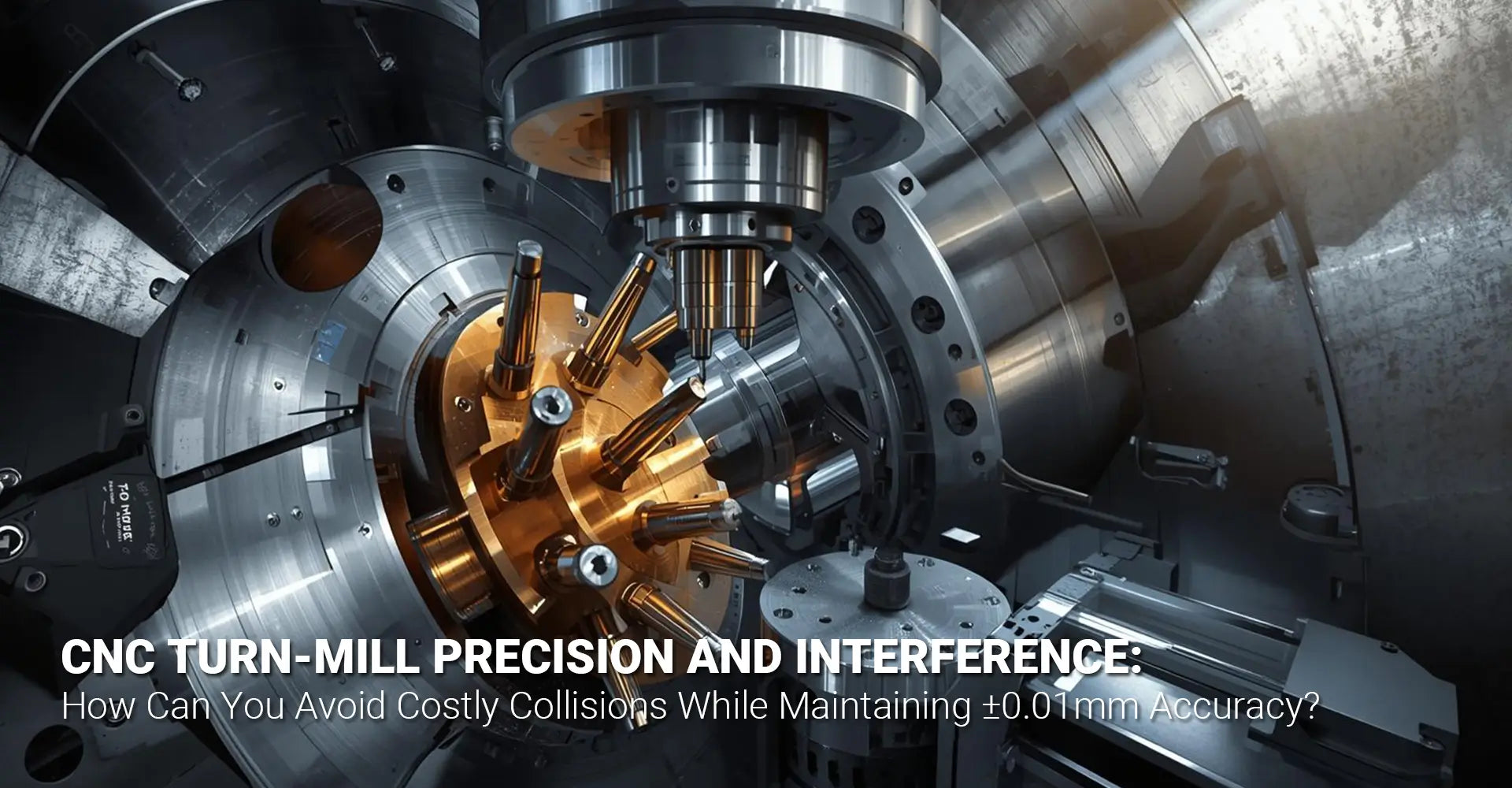
CNC Turn-Mill Precision and Interference: How Can You Avoid Costly Collisions While Maintaining ±0.01mm Accuracy?

Turn-mill machining offers incredible capabilities for producing complex parts in a single setup. However, the combination of rotating workpieces, live tooling, and multiple axes creates significant risks for tool collisions and precision loss. Whether you're programming your first turn-mill job or troubleshooting accuracy issues on an existing setup, understanding CNC turn-mill precision interference is critical for success. This guide provides practical strategies to help you achieve tight tolerances while avoiding the costly mistakes that plague even experienced machinists.
Quick Answer: Key Strategies at a Glance
To maintain ±0.01mm precision while preventing interference in CNC turn-mill operations:
- Verify clearances between tool holders, chuck jaws, and machine components before running programs
- Use full machine simulation with accurate tool assembly models in your CAM software
- Implement thermal management through proper warm-up cycles and temperature-controlled coolant
- Select appropriate tooling with minimal overhang and proper reach-to-diameter ratios
- Calibrate regularly including C-axis positioning and tool length compensation checks
Most Common Interference Points:
- Tool holder collisions with rotating chuck during milling
- Live tooling interference with tailstock or turret components
- C-axis positioning conflicts with workholding fixtures
- Adjacent tool interference during tool changes
Understanding these fundamentals sets the foundation for safe, accurate turn-mill operations. Now, let's dive deeper into each critical aspect of maintaining precision while preventing costly collisions. The following sections will walk you through specific causes, solutions, and best practices that professional machinists use daily.
Table of Contents
- What Causes Interference in CNC Turn-Mill Operations?
- How Can You Maintain ±0.01mm Tolerances Consistently?
- Which CAM Features Prevent Turn-Mill Collisions Most Effectively?
- What Role Does Tool Selection Play in Precision and Safety?
- Conclusion
What Causes Interference in CNC Turn-Mill Operations?
Understanding the root causes of collisions is your first line of defense. Turn-mill centers combine turning and milling capabilities, which means more moving parts and more potential conflict points than traditional machines.
The Five Primary Interference Sources:
The most dangerous interference situations arise from predictable sources that impact turn-mill center accuracy. First, tool holder collisions with the rotating chuck represent the single most common crash scenario. When milling operations engage while the workpiece spins in the chuck, the tool holder body can strike chuck jaws or the chuck body itself. Second, live tooling mounted on the turret may interfere with stationary machine components during complex movements. Third, C-axis rotary positioning can create unexpected collisions when the workpiece rotates into tool paths. Fourth, workholding fixtures and custom chucks often extend beyond standard dimensions, creating clearance issues. Finally, program synchronization problems between turning and milling cycles can cause timing-based collisions.
Preventing These Common Failures:
To avoid these interference scenarios, you need a systematic verification process. Start by creating accurate 3D models of all tool assemblies, including holders, extensions, and cutting tools. Measure your actual workholding setup rather than relying on manufacturer specifications, as custom jaws and fixtures vary. Use your CAM software's collision detection to simulate the entire operation before generating code. Additionally, establish safe zones in your machine coordinate system that tools cannot enter during specific operations. Document these safe zones and reference them during program development.
Machine operators should also conduct dry runs at reduced feed rates for new programs. Watch for any unexpected movements or close clearances. Many modern turn-mill centers include live tooling collision avoidance features in their control software, but these systems only work when properly configured with accurate machine and tool data. Therefore, regularly update your tool library with measured dimensions rather than nominal values. When working with industrial machinery, understanding equipment-specific limitations becomes essential for preventing damage and maintaining production schedules.
How Can You Maintain ±0.01mm Tolerances Consistently?
Achieving sub-0.01mm precision on a turn-mill center requires controlling multiple variables simultaneously. Unlike dedicated turning or milling machines, CNC multi-tasking machine precision faces unique challenges from the combination of operations.
Critical Precision Factors:
Thermal stability forms the foundation of consistent accuracy. Machine structures expand and contract with temperature changes, affecting positioning accuracy. Consequently, implement a proper warm-up routine by running the machine through its travel range for 15-30 minutes before precision work. Use temperature-controlled coolant systems to maintain consistent thermal conditions throughout production runs. Furthermore, environmental factors matter—even shop temperature variations can impact precision on long-running jobs.
Tool deflection represents another significant precision killer in achieving CNC lathe with milling precision. When cutting forces push against the tool, it bends slightly, removing less material than programmed. To compensate, use rigid tool holders with minimal overhang. Select tools with appropriate reach-to-diameter ratios—generally keeping overhang less than 3-4 times the tool diameter. Additionally, program tool pressure compensation into your cutting cycles to account for predictable deflection patterns.
Measurement and Verification Methods:
In-process measurement dramatically improves precision consistency. Install probing systems to verify critical dimensions during machining cycles. Use these measurements to automatically update tool offsets, compensating for tool wear throughout production runs. Moreover, implement regular calibration schedules—checking C-axis positioning accuracy every 500 hours and verifying ballscrew backlash compensation monthly.
Tool runout directly affects surface finish and dimensional accuracy. Check spindle and tool holder runout regularly using dial indicators, maintaining readings below 0.003mm. Replace worn tool holders promptly, as even slight runout compounds in multi-axis operations. Finally, monitor cutting forces through spindle load meters to detect tool wear before it impacts part quality. Professional CNC machining services understand that consistent quality depends on these verification procedures becoming standard practice rather than occasional checks.
Which CAM Features Prevent Turn-Mill Collisions Most Effectively?
Your CAM software serves as the primary collision prevention tool. However, not all CAM systems handle turn-mill complexity equally well. Understanding which features provide real protection helps you program safely and implement effective complex part machining strategies.
Essential CAM Capabilities:
Full machine simulation with accurate kinematic models represents the most critical feature for dynamic collision detection CNC applications. Your CAM system should model not just the tool path, but every moving component—including turrets, tailstocks, and rotary axes. This simulation must update in real-time as you modify programs. Look for systems that highlight clearance violations before they become crashes.
Automatic collision detection should check continuously throughout tool paths. Basic systems only verify at discrete points, potentially missing interference during continuous movements. Advanced CAM software analyzes the entire swept volume of moving components, catching simultaneous machining interference that point-based checking misses. Additionally, the system should check tool holder and tool assembly collisions, not just the cutting tool itself.
Post-Processor Verification and Tool Modeling:
Even perfect simulation fails if your post-processor generates incorrect code. Verify that your post-processor accurately translates CAM paths into machine-specific G-code. Test new post-processors with simple programs first, comparing simulated movements with actual machine behavior. Many crashes occur because post-processors mishandle rotary axis positioning or tool length compensation.
Build complete tool assembly models within your CAM system through effective tool path optimization turn-mill practices. Include exact dimensions for tool holders, extensions, collets, and cutting tools. Measure these components physically rather than using catalog dimensions, as manufacturing tolerances accumulate. Update your tool library whenever you purchase new holders or modify existing assemblies. Some machinists photograph tool assemblies with calipers visible to maintain accurate records.
Material removal simulation provides another verification layer. Watch how the workpiece profile changes throughout the operation. Sometimes clearances that exist at the beginning of a cut disappear as material removes. Dynamic simulation accounts for these changing conditions, preventing collisions that static checking misses. When machining various metals and plastics, material-specific behavior during cutting operations must be considered in your collision avoidance strategy.
What Role Does Tool Selection Play in Precision and Safety?
Tool selection directly impacts both accuracy and collision risk. The right tools maintain precision while fitting safely within machine constraints. Conversely, poor tool choices compromise both dimensions and safety, making turn-mill machine setup tips essential knowledge.
Balancing Reach and Rigidity:
Extended tool holders increase deflection, reducing achievable precision. Every millimeter of unnecessary overhang decreases rigidity and amplifies vibration. Therefore, use the shortest tool assembly that still provides necessary clearance. When extended reach is unavoidable, reduce cutting parameters to minimize deflection forces.
Specialized turn-mill tools are designed specifically for clearance in tight spaces. These tools feature compact holder designs and optimized geometries that reduce interference risk. While initially more expensive, dedicated turn-mill tooling often pays for itself through reduced crash risk and improved cycle times. Additionally, these specialized tools typically provide better chip evacuation in combined turning-milling operations.

Tool Geometry and Collision Avoidance:
Tool geometry affects both cutting forces and potential for interference. Sharp cutting edges reduce forces, minimizing deflection and improving accuracy. However, aggressive geometries may limit clearances in tight spaces. Balance these factors by selecting tools with appropriate edge preparations for your specific application.
Tool assembly verification should happen before every critical job. Physically measure tool projection lengths and compare against programmed values. Check that tool holder tapers are clean and properly seated. Even small discrepancies between actual and programmed tool dimensions can cause collisions or dimensional errors. Furthermore, consider using tool identification systems that automatically verify correct tool installation before machining begins.
Reach-to-diameter ratios provide a practical guideline for tool selection. For finishing operations requiring high precision, maintain ratios below 3:1. Roughing operations can tolerate ratios up to 4:1 or 5:1 with appropriate parameter adjustments. Beyond these ratios, deflection and vibration typically compromise both surface finish and dimensional accuracy. When longer reach is absolutely necessary, consider using damping bars or special boring bars designed for extended reach applications.
Conclusion
Precision turn-mill machining requires careful attention to both accuracy maintenance and interference prevention. By implementing proper thermal management, selecting appropriate tooling, and utilizing comprehensive CAM simulation, you can consistently achieve ±0.01mm tolerances while avoiding costly collisions. Remember that successful turn-mill operations depend on systematic verification at every stage—from initial setup through program development to final production runs.
Start by documenting your specific machine's limitations and safe working zones. Build accurate tool assembly models and verify them physically before running new programs. Use full machine simulation to catch potential collisions during programming rather than at the machine. Finally, implement regular calibration and maintenance schedules to maintain precision over time. These practices may seem time-consuming initially, but they prevent the expensive crashes and scrap parts that result from inadequate preparation.
The strategies outlined in this guide apply across various manufacturing scenarios, whether you're working on prototype development or high-volume production. Mastering turn-mill precision and interference avoidance separates competent machine operators from true manufacturing professionals. Take the time to understand your equipment's capabilities, invest in proper tooling and simulation software, and never skip verification steps—your bottom line will thank you.
External Links and Resources
[CNC turn-mill precision interference][^1]
[turn-mill center accuracy][^2]
[CNC multi-tasking machine precision][^3]
[live tooling collision avoidance][^4]
[dynamic collision detection CNC]()[^5]
[turn-mill machine setup tips][^6]
---
[^1]: Understanding CNC turn-mill precision interference can enhance your machining accuracy and efficiency.
[^2]: Exploring methods to improve turn-mill center accuracy can lead to better product quality and reduced waste.
[^3]: Discover how CNC multi-tasking machines enhance precision in manufacturing, leading to improved efficiency and product quality.
[^4]: Learn about live tooling collision avoidance techniques to prevent costly errors and ensure safe operation in CNC machining.
[^5]: Understanding dynamic collision detection can enhance your CNC machining efficiency and safety.
[^6]: Exploring setup tips can significantly improve your turn-mill machine's performance and precision.


