
CNC Turning Precision Parts: Why Does a New O-Ring Still Leak?
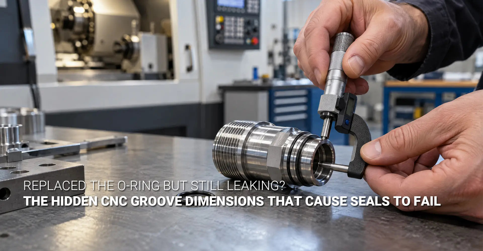
CNC Turning Precision Parts: Why Does a New O-Ring Still Leak?
You changed the O-ring. You tightened the fitting. Then the water came back. This is a leaky coffee machine fitting, and it is more common than most people think. Many people blame the rubber. However, the real cause is often the groove that holds the ring. That groove is cut on a lathe, so even a small cutting error can cause a leak. In this guide, we explain how O-ring groove CNC machining affects sealing. We also show the exact numbers to check. Everything is written in plain words, so you can use it today.

Quick answer: A new O-ring still leaks when the groove is the wrong size or shape. The ring only seals when the groove squeezes it by the right amount. Therefore, check these O-ring groove dimensions first:
| Feature | Target Value | What Goes Wrong |
|---|---|---|
| Depth | Set by a 15–30% squeeze (1.6 mm for a 2.0 mm ring at 20%) | Too deep: the ring is loose and leaks. Too shallow: the ring is crushed. |
| Width | About 1.1–1.3 times the ring's cross-section | Too narrow: the ring pinches. Too wide: the ring rolls. |
| Corner radius | 0.1–0.3 mm | Sharp corners cut the ring. A very large radius shrinks the seal area. |
| Surface finish | Ra 0.8 µm or smoother | Tool marks become tiny leak paths. |
| Runout (TIR) | 0.05 mm or less | Squeeze is uneven around the ring. |
Most readers can stop here. Measure the groove before you replace the ring again. However, if you want the reasons and a full buyer's checklist, keep reading.
These five numbers look small. Yet each one can break a seal on its own. This matters most for coffee machine valve fittings, because hot water, steam, and daily use test every seal. Next, we explain how a groove controls the seal. Then we look at depth and width. After that, we cover the hidden defects that pass a quick check. Finally, we give you a simple checklist for buyers.
[Table Of Contents]
- How Can a Groove Cause a Leak Even With a New O-Ring?
- What Groove Depth and Width Should You Specify?
- How Do Corner Radius, Surface Finish, and Runout Create Hidden Leak Paths?
- How Should Buyers Do O-Ring Groove Inspection Before Releasing an Order?
- Conclusion
How Can a Groove Cause a Leak Even With a New O-Ring?
A new O-ring feels like the perfect fix. It is soft, clean, and the right size. Yet O-ring seal failure often starts in the metal, not in the rubber. The groove decides how the ring sits, how far it is squeezed, and how it moves under water pressure.
An O-ring seals by being squeezed. For static seals, the target squeeze is about 15% to 30%. This O-ring compression is set by the groove. As a result, a wrong groove always means a wrong squeeze.
Picture the O-ring as a soft rubber band sitting in a small channel. The channel walls push on the ring. That push is what stops the water. If the channel is too large, the push is weak. If it is too small, the push is too strong. In both cases, the seal fails.
A CNC turned sealing groove has three main dimensions:
- Depth: this sets how much the ring is squeezed.
- Width: this gives the ring room to move without pinching.
- Corner radius: this protects the ring from cuts and stress.
Two more factors work in the background. They are surface finish and runout. We cover both later in this guide.
So, how can you tell if the ring or the groove is the problem? Use these four steps:
- Inspect the old ring. Look for cuts, flat spots, or swelling. Flat spots can point to too much squeeze. Swelling can point to a chemical attack.
- Measure the groove. Compare the depth, width, and finish with the drawing.
- Test a new ring. If it sits too low or sticks out too far, the groove is wrong.
- Run a pressure test. If the same ring passes in a known-good groove, the first groove is the problem.
Key point: Many reported O-ring failures in coffee machine fittings are really groove size failures. The ring is just the first thing people see.
What Groove Depth and Width Should You Specify?
Depth and width are the first two numbers on any sealing drawing. They are also the two numbers that buyers check first. Because they work together, a mistake in one often hides a mistake in the other.
Groove depth equals the ring's cross-section times one minus the squeeze percentage. This O-ring squeeze calculation takes only one line:
Depth = Cross-Section × (1 – Compression %)
For example, take a 2.0 mm ring with a 20% squeeze. The groove depth is 2.0 × 0.80, which equals 1.6 mm. For width, a common starting range is 1.1 to 1.3 times the cross-section. For the same ring, that is about 2.2 to 2.6 mm.
The O-ring groove depth is the most important number on the drawing. Here is why.
- If the groove is too deep, the ring sits loosely. The squeeze drops below 15%, and water finds a way past. For instance, a 1.75 mm groove gives only 12.5% squeeze on a 2.0 mm ring.
- If the groove is too shallow, the ring is crushed. For example, a 1.4 mm groove gives 30% squeeze on the same ring. At that level, the rubber can take a permanent set. It can also push out into the small gap. This is called extrusion.
Now think about width. The O-ring groove width must hold the full volume of the ring. When the ring is squeezed, it spreads sideways. Therefore, it needs room to spread.
- Too narrow: the ring pinches. Friction rises, and the ring can tear.
- Too wide: the ring can roll or shift under pressure. As a result, it loses its squeeze.
Tolerance matters just as much as the target size. The sealing groove tolerance sets how far the real part can drift from the drawing. Typical values for stainless steel fittings are ±0.05 mm for depth and +0.10 / –0.00 mm for width. Let's test that with numbers. A 1.6 mm target depth with ±0.05 mm tolerance gives a squeeze between 17.5% and 22.5%. That range is safe. However, a loose tolerance could push the squeeze outside the safe window.
Finally, always compare these numbers with the ring maker's design guide. Ring material, water pressure, and seal type can all change the best groove size.
How Do Corner Radius, Surface Finish, and Runout Create Hidden Leak Paths?
Some grooves have the right depth and width, and they still leak. In that case, the problem is usually small and hard to see. Corner shape, surface texture, and alignment can all open a path for water.
Three checks catch most hidden leaks. Aim for a groove corner radius of 0.1 to 0.3 mm. Keep surface roughness at Ra 0.8 µm or lower. Hold runout at 0.05 mm or less.

Let's look at each check in turn.
1. Corner radius. Sharp corners create stress, and they can cut the ring when you press it into place. However, a very large radius eats into the flat sealing area. It can also change the squeeze. For ring sizes up to 2.5 mm, a radius of 0.1 to 0.2 mm usually works. For larger ring sizes, use 0.2 to 0.3 mm.
2. Surface finish. The groove surface finish Ra tells you how rough the metal is. For static seals in water fittings, aim for Ra 0.8 µm (32 µin) or smoother. Dynamic seals need a finer finish, about Ra 0.4 µm. Rough turning marks and chatter act like tiny channels. Water can slip along them, even when the ring is squeezed well. In addition, burrs, scratches, and leftover dirt can cut or lift the ring. For this reason, write the finish on the drawing. Then check it with a profilometer.
3. Runout. Groove runout concentricity describes how well the groove lines up with the bore. If the alignment is off, the squeeze changes around the ring. One side may be loose, while the other side is crushed. The loose side leaks. The crushed side wears out fast. For coffee machine fittings, keep total indicated runout (TIR) at 0.05 mm or less.
What is the best way to hold these numbers? The answer is single-setup CNC turning. In this method, the machine cuts the groove and the bore in one clamping. Because the part never moves, errors do not stack up. As a result, the groove stays centered, the squeeze stays even, and leaks become rare.
How Should Buyers Do O-Ring Groove Inspection Before Releasing an Order?
A report that says "within tolerance" feels safe. However, it can hide real problems. A groove can pass on depth and width, yet fail on finish, radius, or runout. Therefore, buyers need a short and clear plan.
Measure six things on the first article. Then repeat the key checks on every batch. Ask for a written report with real numbers, not just a "pass" stamp.
First-Article Checklist
| What to Measure | Common Tool |
|---|---|
| Groove depth | Depth micrometer or optical comparator |
| Groove width | Caliper or vision system |
| Corner radius | Radius gauge or optical comparator |
| Surface roughness (Ra) | Profilometer |
| Runout to the bore | Dial indicator or CMM |
| Burrs, tool marks, and dirt | Visual check under good light |
Typical Drawing Tolerances
These values are common for CNC-turned grooves in stainless steel fittings. Always confirm them against the ring maker's guide for your exact ring size and material.
| Feature | Typical Tolerance |
|---|---|
| Depth | ±0.05 mm |
| Width | +0.10 / –0.00 mm |
| Corner radius | ±0.05 mm |
| Surface roughness | Ra ≤ 0.8 µm |
| Runout (TIR) | ≤ 0.05 mm |
What to Check on Every Batch
- Depth and width: these two change when a tool wears.
- Visual check: look for burrs and tool marks.
- Spot checks: measure the finish and the corner radius on a few parts.
Questions to Ask Your Supplier
- Do you cut the groove and the bore in one setup?
- Which gauge do you use for depth, and how often do you calibrate it?
- Can you send a report with real values for all six features?
- Do you measure the surface finish with a profilometer?
- Have you made tight-tolerance coffee parts before, such as CNC coffee grinder burrs?
What If the Supplier Says "Within Tolerance" but It Still Leaks?
First, remember that a part can sit at the very edge of the tolerance band. Second, depth and width may pass while finish, radius, or runout fail. So, take these steps:
- Ask for a full report that includes finish and runout.
- Run a pressure decay test on the assembled fitting. In this test, you fill the fitting, close the supply, and watch the pressure for a drop.
- Ask the supplier to review the groove against the ring's real squeeze needs.
- Check the drawing itself. Sometimes the tolerance on the drawing is wrong for the job.
Example scenario (for illustration only): A drawing calls for a 1.6 mm depth with ±0.05 mm tolerance. The report shows 1.65 mm, so the part passes. But the corner is sharp, and the finish is rough. The fitting still leaks. In short, the depth check alone was not enough. A full six-point check would have caught the problem.
Conclusion
A new O-ring cannot fix a bad groove. In most cases, the groove sets the squeeze, guides the ring, and holds the seal in place. Therefore, a quick check of the groove can save you time, money, and repeat repairs.
Here is a short recap:
- Depth sets the squeeze. Use Depth = Cross-Section × (1 – Compression %).
- Width gives the ring room. Start near 1.1 to 1.3 times the cross-section.
- Corner radius protects the ring. Aim for 0.1 to 0.3 mm.
- Surface finish blocks leak paths. Aim for Ra 0.8 µm or smoother.
- Runout keeps the squeeze even. Hold TIR at 0.05 mm or less.
- Single-setup turning keeps the groove and bore aligned.
As a buyer, ask for real numbers on the first article. Then spot-check every batch. If you want a second pair of eyes on your drawing, send it to the Hotean team for a review.
[External links recommendation]
[O-ring groove CNC machining][^1]
[CNC turned sealing groove][^2]
[CNC turned O-ring groove standard] [^4]
[O-ring squeeze calculation] [^5]
[^1]: A peer-reviewed study published in *Transactions of FAMENA* (2025) investigating the effects of cutting speed, feed rate, and depth of cut on surface roughness (Ra) of O-ring groove bases, providing an empirical model for optimising grooving parameters.[reference:16]
[^2]: An article from Quality Magazine (US-based) detailing the use of disk styli for CMM inspection of interior O-ring grooves. It explains that hydraulic component manufacturers depend on disk probes to check interior O-ring grooves, and provides calibration guidance: a minimum of twelve points should be touched on the disk surface (four around the equator and eight distributed around the remaining spherical area). The article notes that disk styli are manufactured from ruby, ceramic, hardened steel, and carbide to suit different part geometries.
[^3]: A comprehensive technical resource from O-Ring-Stocks (Netherlands/EU-based) covering O-ring selection and failure for coffee machines. It details that O-rings should be inspected annually and replaced every 1–2 years, identifies EPDM as the most common material for hot water and steam circuits (resistant up to 120–150°C) and silicone (VMQ) for static seals in brewing units, explains that compression set causes O-rings to lose resilience and determines service life, and lists the relevant food-contact certifications including EC 1935/2004, FDA 21 CFR 177.2600, NSF/ANSI 61, WRAS, and KTW.
[^4]: A comprehensive engineering guide from Somic Custom Parts (US-based) detailing how to specify O-ring grooves on CNC drawings. It explains that O-ring groove geometry is governed by three principles: squeeze, gland fill, and stretch. For static seals, the recommended squeeze range is 15–30%, while dynamic seals drop to 8–20%. Gland fill should never exceed 85%. The guide also references ISO 3601 as the international standard for O-ring grooves and covers groove width and depth callouts, tolerance logic, and machining constraints, making it a practical resource for CNC turned part design.
[^5]: A technical calculation guide from Apple Rubber’s Seal Design Guide (US-based manufacturer) providing step-by-step formulas for determining the correct O-ring cross-section based on gland depth and desired compression. It distinguishes between axial squeeze (face seals) and radial squeeze (piston/rod seals), noting that dynamic applications require lower squeeze to reduce friction. The guide includes a 12-step calculation for maximum O-ring cross-section and a rule of thumb that stretch greater than 5% on the O-ring I.D. is not recommended.