Die Casting Simulation Services: How Do You Know Where Defects Hide Before Cutting Steel?
Die Casting Simulation Services: How Do You Know Where Defects Hide Before Cutting Steel?
Quick Reference: Key Points at a Glance
|
Category |
Key Point |
|
What It Is |
Die casting simulation services use physics-based software to predict metal behavior before any steel is cut. |
|
Core Benefit |
Predict porosity, shrinkage, and cold shuts -- and fix them virtually, not physically. |
|
ROI |
Tooling iterations reduced from 3+ down to 1. Method development time cut by up to 80%. |
|
Who Needs It |
Engineers and procurement teams sourcing HPDC, thin-wall, or complex structural castings. |
|
Top Platforms |
MAGMASOFT, FLOW-3D Cast, ProCAST, Altair Inspire Cast |
|
When to Ask for It |
Before design freeze -- when there is still time to change gate placement, wall thickness, or cooling channels. |
Every die casting project starts with a hard question: will this part be good the first time? For decades, the only honest answer was we will find out when we cut the steel. That meant expensive tooling trials, unexpected porosity, rejected parts, and delayed shipments. Today, a better answer exists -- and it starts with simulation, not steel.
Die casting simulation services use physics-based software to model the entire casting process -- from metal injection to solidification -- before a single cut is made. They predict exactly where defects will form, why they form, and how to prevent them. In short, they turn guesswork into data.
This guide walks you through everything you need to know. First, we cover why traditional die tryouts are so costly. Then, we explain how digital twin technology works. Next, we show what simulation software actually predicts. Finally, we break down the real ROI numbers. By the end, you will know exactly what to ask your die caster -- before it is too late to change anything.
Table Of Content
- What Is the Cut-and-Hope Problem Costing Your Operation?
- What Is a Die Casting Digital Twin -- And How Does It Work?
- What Does Die Casting Simulation Software Actually Predict?
- Does Simulation Actually Deliver Measurable ROI?
- Conclusion & FAQ
What Is the Cut-and-Hope Problem Costing Your Operation?
Traditional die casting development relies on physical trial and error. A mold is designed, steel is cut, and metal is poured. Then the problems show up: shrinkage here, a cold shut there, porosity in the worst possible spot. The team goes back, modifies the tool, and tries again. This cycle repeats -- sometimes three or four times -- before the part is acceptable.
The real cost of one tooling iteration includes:
- Steel cutting and rework: $5,000 to $50,000+ per iteration, depending on mold complexity
- Machine downtime: 2 to 6 weeks per trial cycle
- Engineering hours: 40 to 120 hours of redesign and analysis per iteration
- Delayed launch: every week of delay has downstream supply chain costs
- Scrap material: casting defect prediction is the only way to stop producing defective parts before the run even starts
The deeper problem is structural. Physical tryouts are reactive by design. You can only find a defect after it has already formed. By that point, the mold is cut, the budget is spent, and the timeline is slipping. Simulation flips that dynamic entirely. Problems are found and fixed in software -- where changes cost almost nothing.
This is why leading manufacturers across automotive die casting and high-precision structural components have adopted virtual tryout as a standard step in their development process.
What Is a Die Casting Digital Twin -- And How Does It Work?
A digital twin die casting setup is a complete virtual replica of your casting process. It is not just a 3D model of the mold. It is a living, physics-driven simulation that accounts for how molten metal flows, how heat moves through the die, how pressure builds during injection, and how the part solidifies over time. Think of it as a full test flight -- without ever leaving the computer.
A digital twin for die casting captures these core process variables:
- Injection pressure and fill speed
- Metal temperature and alloy properties (e.g., A380, AlSi12)
- Die temperature and thermal cycling
- Overflow and vent placement
- HPDC simulation: modeling the high-velocity injection dynamics specific to high-pressure die casting
- Solidification time and shrinkage behavior
CAD tells you what the mold looks like. Simulation tells you what the metal will do inside it.
Beyond Fill Patterns: Thermal, Stress, and Solidification All in One Environment
Early simulation tools only showed you how metal filled the cavity. Modern platforms go far deeper. Today's digital twin environments model thermal stress on the die itself -- predicting where thermal fatigue cracks will eventually form. They model residual stress in the part -- identifying distortion risks before machining. They simulate cooling channel performance -- showing whether your water lines are actually removing heat where it matters most.
This level of detail is what makes solidification analysis so powerful. You are not just watching metal flow in. You are watching the entire process -- fill, pack, solidification, ejection -- as a connected system. A change to the gate location in your simulation instantly shows you the downstream effect on porosity and cycle time.
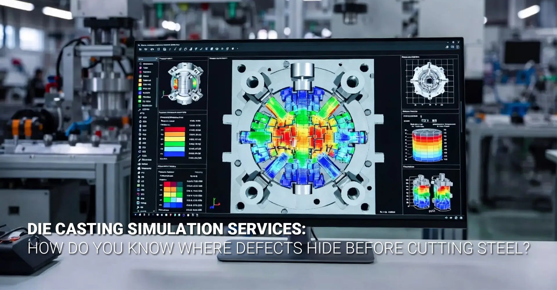
What Does Die Casting Simulation Software Actually Predict?
This is the most practical section for engineers. Simulation software does not give you a single pass/fail score. It gives you a detailed, 3D visualization of every significant defect risk -- color-coded, quantified, and locatable. Here is what each major output actually tells you.
Core simulation outputs and what they predict:
• Flow front behavior (filling simulation): Shows how the metal fills the cavity, frame by frame. Identifies incomplete fill, hesitation marks, and race-tracking -- where metal flows faster down one path than another.
• Air entrapment and gas porosity: With porosity prediction die casting technology, the software maps every location where air gets trapped during injection. These become voids or surface blisters in the finished part.
• Hot spots and shrinkage porosity: Shows where the last metal to solidify will pull away from the wall -- creating internal voids that weaken the part or cause leakage.
• Die thermal cycling: Predicts heat buildup in the die over multiple shots, helping you place cooling channels where they are actually needed.
Flow Front Behavior: Visualizing How Metal Fills the Cavity
Fill visualization is the most intuitive output. You see an animation of metal entering the cavity, and you can immediately spot problems. Does the metal reach a thin wall before it cools too much? Does it create a weld line at a structurally critical location? Does it fold back on itself, trapping air?
Air Entrapment and Gas Porosity: Knowing Exactly Where Pockets Will Form
Air entrapment is the most common cause of surface defects in die casting. Die casting mold flow analysis identifies precisely where air gets pushed into pockets during injection. With this data, engineers can reposition overflows and vents to evacuate the air before the metal arrives. The result is a clean, blister-free surface -- confirmed in software, not on the shop floor.
Hot Spots and Shrinkage: Predicting Solidification Defects Before They Happen
Shrinkage porosity forms when metal solidifies from the outside in, leaving a void at the center of a thick section. Simulation identifies every thick-wall junction where this will happen. Designers can then add material, modify geometry, or redesign cooling to prevent it -- all before cutting steel.
Thermal Cycling: Optimizing Die Life and Cooling Strategies
Thermal fatigue is the leading cause of die failure. Repeated heating and cooling cycles create cracks over thousands of shots. By simulating virtual die tryout conditions across multiple cycles, engineers can spot hot spots on the die surface itself -- and redesign cooling channels to extend tool life significantly.
Does Simulation Actually Deliver Measurable ROI?
This question matters most to engineering managers, procurement leads, and anyone signing off on project budgets. The answer is yes -- and the numbers are well documented. Simulation pays for itself many times over on complex parts. It still delivers positive ROI on simpler geometries when you factor in even one avoided tooling rework.
Documented ROI data from industry case studies:
• Tooling iterations: Reduced from 3+ physical trials down to 1 -- or zero -- in documented automotive and industrial cases
• Method development time: Up to 80% reduction compared to traditional trial-and-error development
• Scrap rate: Shifts quality assurance from detection to prevention -- eliminating defect conditions before the run
• Time-to-market: Faster design freeze, fewer delays, earlier production readiness
Simulation moves quality control upstream -- from the inspection table to the design stage.
Case Evidence: Reducing Tooling Iterations from Three to One
One automotive structural bracket manufacturer producing a high-complexity AlSi10MnMg part for a body-in-white application reduced tooling iteration cycles from three to one after adopting digital twin simulation. The single remaining trial was a process confirmation, not a defect-hunting exercise. Total savings exceeded $120,000 on that single project.
Time Savings: 80% Reduction in Method Development Time
Traditional method development -- deciding on gate placement, overflow positions, and process parameters -- takes weeks of engineering time and multiple physical shots. With reducing tooling trials as the primary goal, simulation compresses this into days of virtual iteration. Engineers run dozens of scenarios in software and arrive at an optimized method before a single production shot is fired.
Scrap Reduction: Moving from Detection to Prevention
For industrial machinery components and kitchen appliance housings where cosmetic and structural quality standards are both high, the shift from detection to prevention is transformative. Scrap found at final inspection -- or worse, at the customer -- is eliminated at the design stage. Simulation is especially valuable here because it identifies defect conditions, not just defect instances.
Available Tools: A Quick Overview of Industry-Standard Simulation Platforms
Not all simulation platforms are equal. Here is a brief overview of the four tools most commonly used by leading die casters:
• MAGMASOFT: A market leader for foundry simulation, strong in solidification analysis and process optimization. Widely used in European and North American automotive supply chains.
• FLOW-3D Cast: Excellent for high-velocity fill simulation and air entrapment prediction. Strong in HPDC applications where metal velocity and turbulence behavior are critical.
• ProCAST: A high-fidelity finite element simulation platform used for structural prediction and residual stress analysis in complex structural castings.
• Altair Inspire Cast: A user-friendly platform popular for rapid feasibility studies and early-stage design validation.
Integration with Die Design: From Simulation to Steel Cutting
Simulation is most powerful when it is fully integrated with the die design process. Simulation outputs directly inform gate and runner layout, cooling channel placement, and overflow positioning -- before design freeze. This integration means that rapid prototyping and tooling development happen in parallel, with simulation data validating each design decision along the way.
When combined with downstream CNC machining services, a simulation-validated casting reduces rework at the machining stage too -- because walls are where they should be, datum surfaces are stable, and porosity is not waiting to be exposed by a drill bit.
Co-Design with Customers: Ensuring Castability Before Design Freeze
The highest-value use of simulation is co-design. When customers share their part geometry and functional requirements early -- ideally before design freeze -- simulation can evaluate multiple geometry options and return a castability verdict. Wall thickness adjustments, rib placement changes, and fillet radii modifications that seem minor on a drawing can have major effects on filling and solidification. Catching them before design freeze costs almost nothing. Catching them after steel is cut costs everything.
Conclusion
Die casting simulation services are not a luxury for large OEMs. They are a practical, well-proven tool for any manufacturer who wants to reduce risk, save money, and deliver better parts faster. The technology is mature. The ROI is documented. The only question is when you start using it -- before the steel is cut, or after the problems show up.
Here is a simple checklist to take into your next die caster conversation:
• Does your die caster offer simulation as a standard service -- or only on request?
• Which platform do they use? (MAGMASOFT, FLOW-3D Cast, ProCAST, or Altair Inspire Cast)
• Will they share the simulation report, including porosity prediction maps?
• Can they co-design with you before design freeze?
• How many tooling trials do they typically need -- and how does simulation change that number?
Frequently Asked Questions
Q1: What exactly is die casting simulation, and how is it different from just designing a mold in CAD?
CAD tells you what the mold looks like. Simulation tells you what the metal will do inside it. Die casting simulation uses physics-based solvers to model the actual behavior of molten metal during injection, flow, and solidification. It predicts where air will be trapped, where hot spots will form, and where shrinkage porosity is likely to occur -- information you cannot get from a static CAD model. It is the difference between a blueprint and a test flight.
Q2: Can simulation really predict exact defect locations -- including porosity?
Yes, with remarkable accuracy. Modern simulation software provides color-coded 3D visualizations showing precisely where air entrapment and shrinkage porosity are likely to occur. This allows designers to modify wall thicknesses, adjust gate locations, or reposition overflows before any steel is cut -- eliminating guesswork and avoiding expensive mold modifications later.
Q3: How many trial runs can simulation realistically save on a new die casting project?
Industry case studies show reductions from 3+ physical trials down to 1 -- or even zero -- in some cases. One automotive component manufacturer reduced tooling iteration cycles from three to one after implementing mold flow analysis. Another foundry achieved an 80% reduction in method development time. The savings in tooling steel, machine downtime, and labor are substantial.
Q4: What information do I need to provide to get a meaningful simulation report from my die caster?
You need a high-resolution 3D CAD model of the part (with draft, fillets, and wall thicknesses), the alloy specification (e.g., A380, AlSi12), and expected production parameters (injection pressure, die temperature, desired cycle time). The more accurately you define the intended process, the more predictive the simulation results will be.
Q5: Is simulation only useful for complex, high-volume parts, or does it help with simpler geometries too?
While the ROI scales with complexity, even simple parts benefit. Unseen defects like micro-porosity or subtle flow imbalances can affect sealing surfaces or machined features in any part. For thin-walled parts, simulation ensures complete fill. For multi-cavity dies, it confirms uniform flow across all cavities. This is especially relevant for automotive components where zero-defect standards apply regardless of part complexity.
Q6: What are the most common defects that simulation helps prevent?
Simulation is routinely used to predict and prevent:
• Gas porosity / air entrapment (surface blisters, internal voids)
• Shrinkage porosity (weak spots, leakage paths)
• Cold shuts / misruns (incomplete filling)
• Die erosion (from excessive gate velocity)
• Residual stresses and distortion
Recommended External Resources
For further reading on die casting simulation and process validation, these authoritative sources are worth exploring:
• MAGMASOFT Official Resource Library -- technical documentation, case studies, and webinars on foundry simulation
• FLOW-3D Cast Case Studies -- application examples for HPDC and other casting processes
• ESI ProCAST Documentation -- finite element casting simulation for structural and thermal analysis
• North American Die Casting Association (NADCA) -- industry standards, process guidelines, and technical white papers
[Die casting simulation services][^1]
[die casting mold flow analysis][^2]
[casting defect prediction][^3]
[HPDC simulation][^4]
[virtual die tryout][^5]
[FLOW-3D Cast][^6]
[^1]. details the expert services in die design, runner concepts, and advanced casting simulations to optimize part quality and process stability
[^2]. this resource explains the technical importance of mold flow simulation in zinc die casting, focusing on how it predicts metal velocity, temperature, and pressure to eliminate defects during the desiThisgn stage.
[^3]. This discusses how advanced casting simulation software can predict up to 90% of design-related defects, such as shrinkage and porosity, before production begins.
[^4]. this resource explores the technical benefits of High Pressure Die Casting (HPDC ) simulation, highlighting its role in reducing scrap, optimizing cycle times, and preventing common defects like cold laps and air entrapment.
[^5]. This resource explains the concept of virtual die tryout (also known as computerized die tryout ), detailing how simulation allows engineers to evaluate part viability and die design to reduce tool recuts and optimize the stamping process before physical construction.
[^6]. this resource provides specialized workspaces for various processes, offering accurate flow modeling, defect detection, and optimization tools for high-quality casting solutions.
1 comment


This is a great breakdown of the ROI on simulation—reducing tooling trials from 3 to 1 is a massive operational win. Since you mentioned the integration with CNC services and co-designing with customers, I’m curious about the logistical side for those of us looking to set up manufacturing operations or R&D branches in Europe to be closer to these die-casting facilities. When moving from the simulation stage to actually establishing a legal business presence in Spain or Portugal to manage these contracts, has anyone here used digital residency services like https://e-residence.com/it/ to fast-track the NIF/NIE or corporate registration process? I’m trying to figure out if streamlining the administrative “digital twin” is as effective for saving time as the MAGMASOFT simulations are for the technical side.