Why Your Sheet Metal Flat Pattern Never Fits And How to Fix It Before You Send the File?
Why Your Sheet Metal Flat Pattern Never Fits And How to Fix It Before You Send the File?

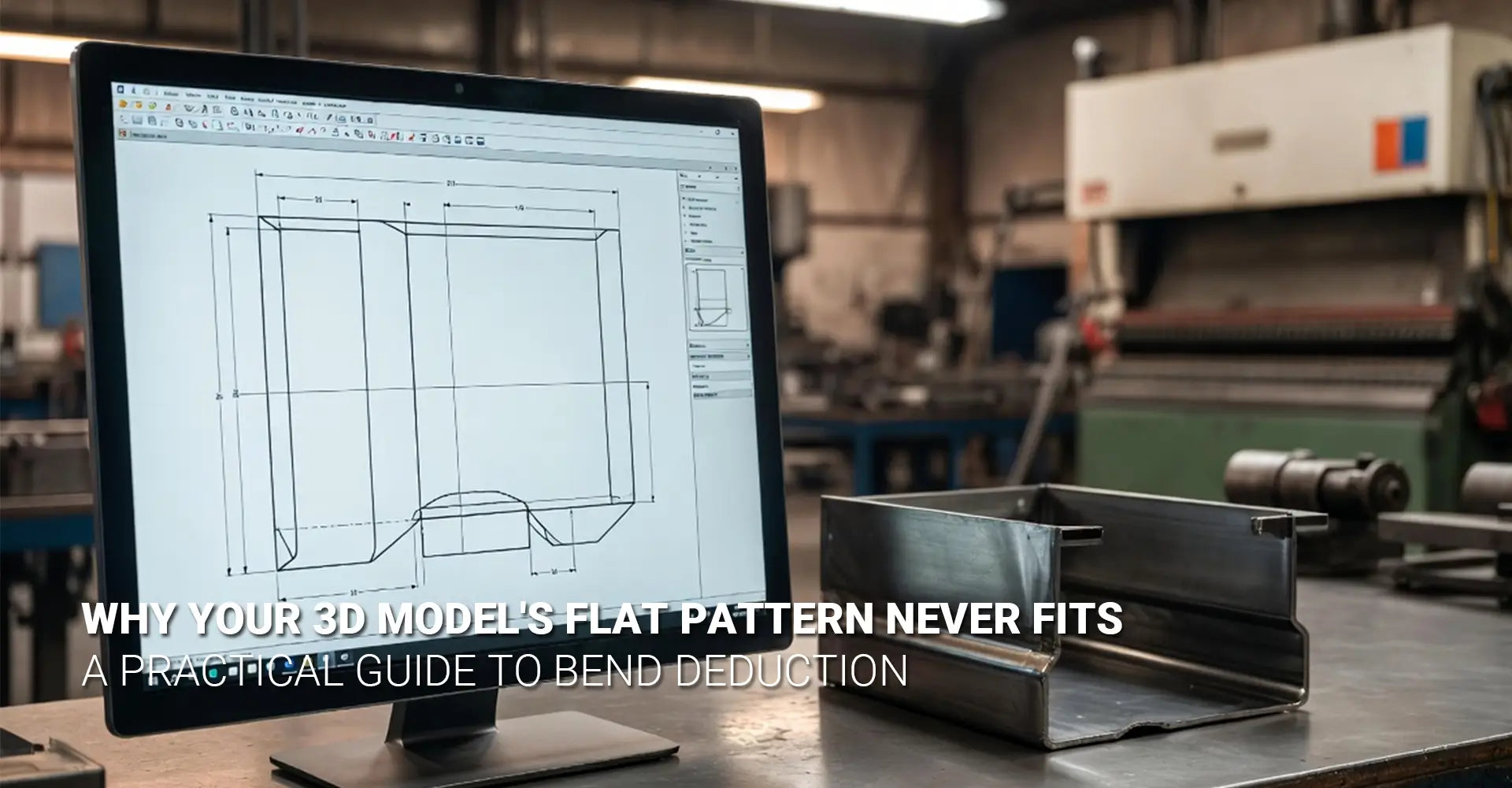
You spent hours building a precise 3D model. The geometry is clean. The tolerances look right. Then the shop calls back — your flat pattern is off again. Sound familiar? This is one of the most common frustrations in sheet metal fabrication. The problem is almost never your design skills. Instead, it comes down to a gap between what your CAD software assumes and what actually happens inside a real press brake.
This guide breaks down exactly why flat patterns go wrong — and gives you a clear, practical fix. Whether you work with aluminum, steel, or stainless, the same root causes apply.
⚡ Key Takeaways — What You'll Learn
- Why CAD default K-factors don't match real-world bending results
- How material choice (aluminum vs. steel) changes your flat pattern math
- Why V-die selection is the hidden variable most designers ignore
- A 4-step process to sync your CAD model with your supplier's press brake
- Quick-reference bend deduction values for common materials
Quick Answer: Sheet metal flat pattern errors happen because CAD software uses theoretical default values — not your supplier's actual tooling, material temper, or V-die setup. To fix it, replace your CAD defaults with shop-tested K-factor values provided by your fabrication partner. Then run a test bend to verify before committing to a full production run.
Now that you know the core issue, let's dig into the details. First, we need to understand what physically happens to metal during a bend. Then we can explore how material, tooling, and workflow choices each play a role. By the end, you'll have everything you need to stop guessing and start getting parts right the first time.
Table of Contents
- What Actually Happens to Metal Inside a Press Brake?
- Does Your Material Choice Really Change the Bend Deduction Numbers?
- Is Your V-Die Width the Real Reason Your Flat Pattern Is Off?
- How Do You Match Your CAD Model to Your Supplier's Press Brake — Step by Step?
- Conclusion + Flat Pattern Accuracy Checklist
- FAQ
What Actually Happens to Metal Inside a Press Brake?
Before you can fix a flat pattern problem, you need to understand what causes it. When a press brake pushes a punch into sheet metal over a V-die, the metal does not simply fold cleanly in half. Instead, it stretches and compresses at the same time — and this material stretch bending behavior is what throws off your flat pattern calculations. The outside of the bend stretches longer. The inside compresses shorter. And somewhere in between, a thin band of material called the neutral axis stays roughly the same length.
The Key Difference:
- Bend Allowance = the arc length along the neutral axis (added to each flat leg to get total flat length)
- Bend Deduction = the amount subtracted from the combined leg lengths to get the correct flat blank size
- Your CAD software uses one or the other internally — knowing which one matters for troubleshooting
K-Factor: The Number That Controls Everything
The position of the neutral axis is described by a ratio called the K-factor. In simple terms, k factor sheet metal = the distance from the inside bend surface to the neutral axis, divided by the total material thickness. A K-factor of 0.5 means the neutral axis sits exactly in the middle of the material.
Most CAD software defaults to a K-factor of 0.44 or 0.5. These are theoretical averages. They do not account for your specific material alloy, its temper, your supplier's V-die width, or their press brake's tonnage. That's why parts come out wrong — the software is making an educated guess that doesn't match reality.
The good news? Once you replace the default K-factor with a shop-tested value from your actual sheet metal bending services partner, your flat patterns become dramatically more accurate.
Does Your Material Choice Really Change the Bend Deduction Numbers?
Absolutely — and this is where many designers get caught off guard. The type of material you choose directly affects how the metal behaves under pressure. Aluminum bending vs steel bending is not just a matter of hardness. Aluminum and steel respond to bending forces in fundamentally different ways. Using the wrong bend deduction values for your material is like using a recipe for bread when you're baking a cake — the process looks similar, but the results won't match.
Material at a Glance:
Property Aluminum (5052-H32) Mild Steel (A36) Stainless Steel (304) Springback High Low–Medium Medium–High Typical K-Factor 0.40–0.45 0.44–0.50 0.44–0.50 Bend Radius Sensitivity High Medium Medium Grain Direction Impact Significant Moderate Moderate
Aluminum's Springback Problem
Aluminum has a lower modulus of elasticity than steel. In practical terms, that means it tries harder to return to its original flat shape after the punch releases. This springback is why aluminum parts often need the press brake to overbend slightly past 90° to achieve a true 90° final angle. And because springback changes the effective bend angle, it also affects your flat pattern length.
Furthermore, not all aluminum is the same. 5052-H32 is soft and formable — great for tight bends. But 6061-T6 is harder and more springback-prone, and it can crack on tight radii. Using 5052 bend deduction values for 6061 parts will consistently produce out-of-tolerance results. Always specify the exact alloy and temper on your drawing — for example, 5052-H32 vs. 6061-T6 — and use separate, validated bend data for each.
Steel: More Consistent, But Not Universal
Mild steel (A36 or 1018) is the most predictable material for bending. It has lower springback and responds more consistently to standard K-factor defaults. However, stainless steel (304) work-hardens as it bends — meaning it gets harder and springier as the punch pushes in. This means stainless often needs adjusted deduction values compared to mild steel, even at the same thickness.
Don't Forget Grain Direction
Sheet metal has a grain direction from the rolling process. Bending across the grain (perpendicular to the roll direction) is generally safer and produces more consistent bend radii. Bending with the grain (parallel to the roll direction) increases the risk of cracking — especially in aluminum. This is a core DFM sheet metal principle that many designers overlook until a part fails in production. Always note grain direction sensitivity on your drawing when it matters.
Is Your V-Die Width the Real Reason Your Flat Pattern Is Off?
Here's the insight that surprises most designers: even if you specify the exact same material and thickness, your flat pattern can still come out wrong if you're bending on a different press brake with a different V-die. The V-die opening width is one of the most powerful variables in the bending equation — and it's almost never shown on an engineering drawing. This is why the same part can measure correctly at one shop and come out wrong at another. Understanding v-die selection is critical for anyone doing serious sheet metal design.
The Rule of 8 (Quick Reference):
A common industry guideline is: V-die opening = 8× material thickness for most standard bends.
- For 3mm (0.120") mild steel → use approximately a 24mm V-die opening
- For 1.5mm (0.060") aluminum → use approximately a 12mm V-die opening
Note: This is a starting point. Your supplier may use different ratios based on their equipment and the bend quality required.
Why V-Die Width Changes Your Bend Deduction
A wider V-die opening causes the metal to bend over a larger radius. This shifts the neutral axis position — which changes the K-factor — which changes your bend deduction. Two shops using the same material and the same CAD file can produce different flat pattern lengths if their V-die widths differ.
This is why a generic bend allowance chart from the internet is only a starting point. Charts typically assume a specific V-die ratio. If your supplier uses a different ratio, the chart values won't apply. The only reliable way to get accurate numbers is to ask your supplier directly what tooling they use — and then test.
"The single most important question you can ask your sheet metal supplier: 'For this material and thickness, what V-die width do you use, and what K-factor should I input in my CAD?' That one question tells them you understand the process — and gets you the exact number you need."
Same Machine, Different Results?
Even on the same press brake, switching to a different V-die tooling set for a different job — then switching back — can introduce variation. Shops that run high-mix production may use several V-die sizes in a single day. For precision sheet metal prototyping, always confirm the specific tooling used on your part before trusting any bend data.
How Do You Match Your CAD Model to Your Supplier's Press Brake — Step by Step?
Now for the practical fix. The goal is simple: replace the theoretical defaults in your CAD software with real numbers that match your specific supplier's equipment and process. Once you do this, your flat patterns will stop being guesswork and start being predictable. Here is a proven 4-step workflow used by experienced precision sheet metal fabrication teams.
One Question That Fixes Most Problems:
Ask your supplier: "For [material type] at [thickness], what V-die width do you use, and what K-factor or bend deduction value should I enter in my CAD software to match your press brake?"
This one question communicates that you understand the process — and it gives you the exact number you need right away.
Step 1: Ask Your Bending Partner for Their "Shop Floor K-Factor"
Call or email your supplier before you finalize your design. Tell them the material type, alloy, temper, and thickness. Ask for the K-factor or bend deduction value they recommend for their equipment. A good fabrication partner — especially one offering sheet metal bending services — will have this data ready.
Step 2: Run a Simple Test Bend and Back-Calculate Your Actual Deduction
Have your supplier bend a simple 90° L-bracket from your exact material on their equipment. Measure the outside dimensions of the bent sample precisely. Then use a bend deduction calculator to back-calculate the real K-factor from those measured values. This removes all assumptions and gives you a number grounded in physical reality.
Step 3: Create Material-Specific Bend Tables in Your CAD Software
Most professional CAD packages (SOLIDWORKS, Inventor, Fusion 360) allow you to build custom bend tables. Create a separate table for each material you use regularly — for example, one for 5052-H32 aluminum at 0.080", one for 304 stainless at 0.060", and so on. These tables should reference the verified, shop-tested K-factor values — not the software defaults. This is a core best practice in sheet metal design tips for any serious design team.
Step 4: Document and Share with Your Team
Once you have verified bend data, save it somewhere your whole team can access. A shared spreadsheet, a folder in your PDM/PLM system, or even a printed chart on the wall all work. The goal is to make sure that every designer on your team uses the same validated data — not whatever CAD default happened to be installed on their machine. Consistent data means consistent parts across every project.
A Note on Surface Finish and Part Inspection
Once your flat pattern is correct, don't forget that surface finish decisions can also affect dimensional outcomes. Thick anodize or powder coat on aluminum, for example, adds measurable build-up on bend edges. For tight-tolerance assemblies, always account for post-process coating thickness in your design.
And if your parts will go into demanding environments — such as kitchen appliances or industrial machinery — the stakes of a wrong flat pattern are even higher. A single out-of-tolerance bend in a structural enclosure can cause assembly failures that are costly to fix after the fact.
Conclusion
Sheet metal flat pattern errors are frustrating — but they are completely solvable. The root cause is almost always the same: your CAD software is using a theoretical default that doesn't match your supplier's real-world tooling and process. Once you understand that bend deduction is driven by K-factor, material behavior, and V-die width working together, the fix becomes clear.
Stop trusting CAD defaults blindly. Start talking to your fabrication partner early. Run a test bend. Build material-specific bend tables. And document the data so your whole team benefits. These are the habits that separate designers who consistently produce accurate parts from those who are always chasing their flat patterns.
✅ Flat Pattern Accuracy Checklist
- Confirm material alloy, temper, and thickness with your supplier before designing
- Ask your supplier for their shop-floor K-factor for your specific material and V-die setup
- Run at least one test bend on your exact material before committing to production
- Use a bend deduction calculator to back-calculate K-factor from measured test parts
- Replace CAD default K-factors with your validated shop-tested values
- Create separate, named bend tables in your CAD for each material you use regularly
- Note grain direction sensitivity on drawings for aluminum parts
- Specify bend radius clearly — never leave it as "sharp" unless you mean it
- Indicate critical vs. reference dimensions on your drawing
- Account for surface finish build-up on tight-tolerance bend edges
- Share your validated bend table data with your entire design team
Frequently Asked Questions
Q: I designed a part in SOLIDWORKS using the default K-factor. The flat pattern came out wrong. What happened?
You ran into the most common pitfall in sheet metal design. Default K-factors (often 0.44 or 0.5) are theoretical averages — not actual measurements. They don't account for your material's specific temper, your supplier's V-die width, or their press brake's tonnage. The solution is to replace the software default with a shop-tested K-factor from your fabrication partner.
Q: Does aluminum really behave that differently from steel in bending?
Significantly. Aluminum has higher springback than mild steel, meaning it tries to return to its flat state after the bend. It also has a lower modulus of elasticity, so it stretches differently under tension. Using steel bend deduction values for aluminum parts will consistently produce undersized flat patterns.
Q: Can I use the same bend deduction for 5052 aluminum and 6061 aluminum at the same thickness?
Not safely. 5052-H32 is soft and formable, while 6061-T6 is stronger but more prone to cracking on tight bends. The springback and bend radii characteristics differ enough that using one alloy's values for the other will produce out-of-tolerance parts. Always validate bend data for each specific alloy and temper you specify.
Q: What is a "bender-friendly" drawing?
Experienced press brake operators appreciate drawings that:
- Specify the bend radius clearly (don't leave it as "sharp" unless you mean it)
- Indicate grain direction sensitivity — especially for aluminum
- Call out critical dimensions vs. reference dimensions
- Show bend orientation consistently throughout the drawing
- Include material temper (e.g., 5052-H32 vs. 6061-T6 — they bend differently)
Q: Is there a universal bend deduction chart I can trust?
Be cautious. Published charts are excellent starting points, but they assume specific tooling and technique that may not match your supplier's setup. The most reliable approach is to develop your own validated data in collaboration with your fabrication partner — creating custom bend tables that reflect their actual capabilities.
Recommended Resources
Online Bend Allowance Calculator (OmniCalculator) — Use this to back-calculate your real K-factor from measured test parts
SOLIDWORKS Bend Table Documentation — Official guide to creating material-specific bend tables in SOLIDWORKS
[Sheet metal bending services][^1]
[sheet metal flat pattern error][^2]
[aluminum bending vs steel bending][^4]
[material stretch bending][^5]
[v-die selection][^6]
[^1]. This provides detailed technical specifications on materials, finishes, and precision tolerances for industrial applications.
[^2]. This expert guide addresses common design mistakes in sheet metal fabrication, including critical errors in flat pattern development, material selection, and tolerancing that can lead to manufacturing failures.
[^3]. This comprehensive article from The Fabricator, a leading publication for the metal forming and fabricating industry, provides an in-depth explanation of the K-factor, its role in calculating bend allowance, and how it shifts the neutral axis during the bending process.
[^4]. This guide compares the mechanical properties and bending behaviors of aluminum and steel, highlighting key differences in springback, ductility, and work hardening that engineers must consider for successful metal fabrication.
[^5]. This resource from Global Forming explains the stretch bending metal forming process, a cold-bending technique that maintains constant tension to achieve superior accuracy, reduce spring-back, and eliminate wrinkles in complex curved profiles.
[^6]. This technical guide provides a comprehensive framework for press brake V-die selection, including the "Rule of 8" for determining ideal die openings based on material thickness to ensure precise, safe, and repeatable bending results.


