CW510L or 316L: Which Machined Stainless Steel Parts Strategy Cuts Your Costs?
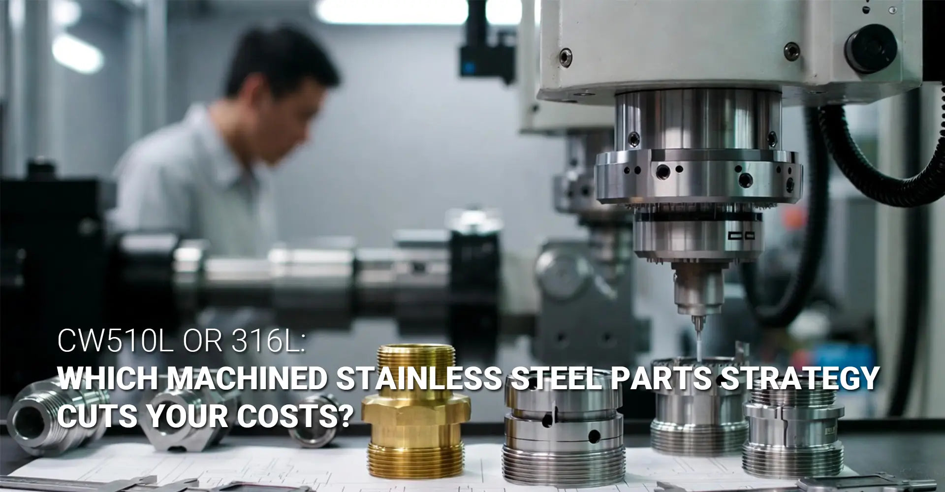
CW510L or 316L: Which Machined Stainless Steel Parts Strategy Cuts Your Costs?
New export rules are pushing many buyers away from leaded brass. As a result, procurement teams often reach for 316L stainless steel by default, without checking the numbers first. That default choice can quietly raise your machining bill. This guide compares two real paths for machined stainless steel parts production: a lead-free brass alloy called CW510L, and standard 316L stainless steel. You will see where each material wins, where it struggles, and what to ask your supplier before you commit to either one.
Hotean produces both alloy families across its CNC machining service lines, including fittings and fluid-contact parts used in coffee equipment. That mix of work gives a clear view of how these two materials behave in daily production, not just in a lab test.
Key Takeaways
| Factor | CW510L Eco Brass | 316L Stainless Steel |
|---|---|---|
| Machinability rating | ~60% (vs. free-cutting brass) | ~40% (vs. free-machining steel) |
| Lead-free / RoHS status | Yes, by design | Yes, naturally lead-free |
| Main tool problem | Long chips, built-up edge | Work hardening, fast tool wear |
| Best tool coating | TiAlN or DLC carbide | AlCrN or nanocomposite PVD |
| Coolant need | Flood coolant usually works | High-pressure coolant strongly advised |
| Best fit | Connectors, fittings, hardware | Marine, chemical, medical parts |
If you need a fast answer: CW510L is roughly a third easier to machine than 316L, but only if your supplier uses the right tooling and coolant setup. Skip that setup, and CW510L can wear tools out almost as fast as stainless does. The choice between these two materials should follow your part's real corrosion and strength needs, not habit.
Many procurement teams assume that switching away from leaded brass automatically means switching to stainless steel. That assumption is where most of the extra cost comes from. Lead-free brass and stainless steel solve different problems, and mixing them up on a quote sheet can add weeks to a project and dollars to every part.
Below, we break down why each material behaves the way it does, then walk through the tooling, coolant, and cutting parameters that keep costs under control. A short table of contents follows, so you can jump straight to the section you need.
Table of Contents
- Is Lead-Free Brass Really Harder on Your Tools?
- How Does 316L Stainless Compare on the Shop Floor?
- What Tooling and Coolant Setup Actually Solves This?
- Which Cutting Parameters and Material Should You Specify?
- Conclusion
Is Lead-Free Brass Really Harder on Your Tools?
Older leaded brass alloys machine easily because lead acts like a built-in lubricant. It breaks chips apart and reduces friction at the cutting edge. Lead-free alloys do not have that helper. This is the trade buyers make when they switch to a compliant material.
In short: yes, lead-free brass is harder on tools, but not by a huge margin, and the gap is easy to close with the right setup.

CW510L, also known as Eco Brass, is a copper-zinc alloy built around an alpha-plus-beta phase structure. This structure cuts differently than single-phase brasses. Without lead, the material forms longer, more continuous chips. Cutting force also runs higher than it does with leaded brass. Together, these two effects raise heat and mechanical load at the tool tip.
CW510L Eco Brass machining work generally shows three related problems. First, long chips can wrap around the tool or the part, so chip control matters more than usual. Second, tool load runs higher, which shortens tool life if the setup is not adjusted. Third, and most important, the material shows a real risk of edge buildup during cutting. This is often called built-up edge prevention in supplier documentation, and it deserves its own line item on any quote you request.
Built-up edge happens when soft workpiece material welds onto the tool surface mid-cut. Once that happens, the tool's effective shape changes. Surface finish drops. Cutting force rises further. In bad cases, the built-up material breaks off and embeds itself in the part, which can fail inspection outright.
The upside is that CW510L's overall lead-free brass machinability still beats stainless steel by a wide margin. Reported ratings put CW510L at roughly 60 percent of free-cutting brass performance. That is a workable number for high-volume connector, hardware, and fitting production, especially through custom CNC milling services that can adjust tool paths and speeds part by part rather than using one fixed program for every job.
How Does 316L Stainless Compare on the Shop Floor?
316L stainless steel is the material many buyers reach for automatically when a part needs corrosion resistance. It earns that reputation. However, it comes with a machining cost that is easy to underestimate at the quoting stage.
In short: 316L is roughly a third less machinable than CW510L, and its tool wear pattern is less forgiving.
Reported machinability for 316L sits near 40 percent relative to a free-machining steel reference. That is meaningfully lower than CW510L's 60 percent figure. The reason ties back to chemistry. High chromium and nickel content give 316L its corrosion resistance, but that same chemistry resists cutting.
The bigger daily problem is work hardening stainless steel behavior. Every time a cutting edge passes over 316L, the surface layer stiffens slightly. If the tool rubs instead of cutting cleanly, even for a moment, that hardened layer gets thicker. The next pass then meets a harder surface, which wears the tool faster and can trigger a feedback loop of rising heat and rising hardness.
This is why 316L stainless steel CNC turning programs look different from brass programs on paper. Speeds run lower. Feed rates stay steady rather than tapering off, because a tool that dwells or rubs feeds the work-hardening problem directly. Depth of cut also gets chosen carefully, since a cut that is too shallow rides on the hardened layer instead of cutting through it.
For a deeper look at how these mechanical properties play out across different stainless grades and part types, our stainless steel in CNC machining resource covers grade selection in more detail. The short version for procurement: budget for slower cycle times and more frequent tool changes when 316L is genuinely required, and treat any quote that ignores this as optimistic.
What Tooling and Coolant Setup Actually Solves This?
Both materials share one truth: the right tooling and coolant setup closes most of the cost gap between them. This is the section to bring to your supplier conversation if you want a straight answer on capability.
In short: coated carbide tools plus the correct coolant delivery method solve the majority of problems in both CW510L and 316L.
For CW510L, coating choice makes a real difference. TiAlN-coated carbide tool coating for brass applications has shown the lowest wear among tested carbide systems, largely because the coating reduces the friction that drives built-up edge formation. DLC coating performs well too, particularly for parts that need a fine surface finish. For very high-volume runs, polycrystalline diamond tooling can pay for itself, though the upfront tool cost is higher.
Surface quality after machining also depends heavily on this tooling choice, and our surface finish page walks through how coating selection and cutting parameters interact with post-machining finishing steps. If your parts need a clean finish straight off the machine, this is worth reviewing before you lock in a tool spec.
For 316L, the bigger lever is coolant delivery rather than coating alone. Flood coolant often cannot break through the vapor barrier that forms at the cutting edge during stainless machining. High-pressure through-spindle coolant, typically run at 70 bar or higher, punches through that barrier directly at the tool tip. This single change reduces heat buildup, limits work hardening, and extends tool life meaningfully. CW510L can also benefit from through-spindle coolant, though it is less strictly required than it is for stainless.
Which Cutting Parameters and Material Should You Specify?
Once tooling and coolant are settled, cutting parameters are the last lever available to control cost. This section gives you the numbers to ask your supplier to confirm.
In short: depth of cut and feed rate drive CW510L cost, while speed and coolant pressure drive 316L cost.
For CW510L, depth of cut and feed rate are the two most influential factors for both cutting force and surface roughness. Published optimization work on similar lead-free brass alloys found favorable results near a cutting force of 34.59 N and a surface roughness of 1.22 micrometers. Typical starting parameters run a spindle speed of 3,000 to 5,000 RPM, a feed rate of 0.15 to 0.3 millimeters per revolution, and a depth of cut between 1 and 3 millimeters, paired with standard flood coolant.
These specific lead-free alloy cutting parameters are a starting point, not a fixed rulebook. Every shop should validate them against its own tooling and machine setup, since spindle rigidity and tool geometry both shift the ideal numbers slightly. For a closer look at how turning parameters are set and adjusted in practice, our CNC turning page covers the process step by step.
Heat treatment offers an added path to better results. Annealing CW510L at 775 degrees Celsius for 60 minutes has been shown to improve surface finish by around 30 percent, largely by increasing the volume of beta-phase material available for clean chip separation. This is a strong option for buyers running high volumes of the same part.
For 316L, the priority order flips. Coolant pressure and cutting speed matter more than depth of cut. Lower speeds paired with high-pressure coolant reduce the risk of work hardening far more reliably than adjusting depth of cut alone. Coated tools, particularly AlCrN systems, have shown close to double the tool life of uncoated carbide on 316L, which is a meaningful factor in overall tool life optimization across a production run.
Conclusion
Which Material Should You Specify for Your Next Export Run?
The honest answer depends on what your part actually needs, not on which material sounds safer. CW510L Eco Brass fits connectors, fittings, and general hardware where RoHS compliance and cost efficiency matter more than extreme corrosion resistance. 316L earns its higher machining cost only where marine, chemical, pharmaceutical, or high-strength conditions genuinely demand it.
The machining cost gap between these two materials is real, and it is large enough to affect a quote. Choosing CW510L over 316L for a part that does not need stainless-grade resistance can lower your per-part cost meaningfully, without any compromise on your compliance goals. Choosing 316L when the application truly calls for it is still the right call, provided your supplier has the coolant and tooling setup to control the cost that comes with it.
Before your next order, ask your supplier three direct questions: what tool coating they run for each material, whether they use high-pressure through-spindle coolant, and what cutting parameters they validate against for your specific part geometry. A supplier who answers all three clearly is one who understands the real cost drivers behind machined stainless steel parts and lead-free brass alike.
It also helps to ask for a sample run before committing to a full production order, especially on a part you have not sourced before. A short trial batch shows you real cycle times, real tool wear, and real surface finish, rather than numbers pulled from a general catalog. That small step upfront can save far more than it costs, and it gives you a clear baseline to compare against future quotes from other suppliers.
For further detail on grade selection, finishing options, and turning setup discussed in this guide, explore the related resource pages linked throughout the sections above.
Recommended Resource
[CW510L Eco Brass machining][^1]
[lead-free brass machinability][^2]
[316L stainless steel CNC turning][^3]
[built-up edge prevention][^4]
[high-pressure through-spindle coolant][^5]
[work hardening stainless steel][^6]
[^1]: A 2026 peer-reviewed study (Procedia CIRP, Elsevier) investigating high-pressure cooling (HPC) effects on CW510L machining. HPC at 60 bar significantly improved chip breakability; main cutting force decreased from ~1900–2000 N to 1450–1550 N as speed increased to 320 m/min, while thrust force dropped from ~1100–1150 N to 600–700 N.[reference:1]
[^2]: A 2018 open-access MDPI journal article (Metals) evaluating CW510L machinability in turning mode against leaded CuZn39Pb3. Using Taguchi L16 DOE methodology, identified depth of cut and feed rate as most influential factors; optimized parameters achieved cutting force of 34.59 N and surface roughness of 1.22 μm.[reference:5]
[^4]: A 2023 Elsevier (ScienceDirect) research article on adhesive wear of TiAlN coatings during low-speed turning of 316L stainless steel, analyzing the adhered layer and BUE formation on worn Ti₁₋ₓAlₓN coated WC-Co cutting tools.[reference:6]