Is Your Supplier Selling You Air? Cut 3D Printing Costs 40% with Smarter Infill Design?
Is Your Supplier Selling You Air? Cut 3D Printing Costs 40% with Smarter Infill Design?

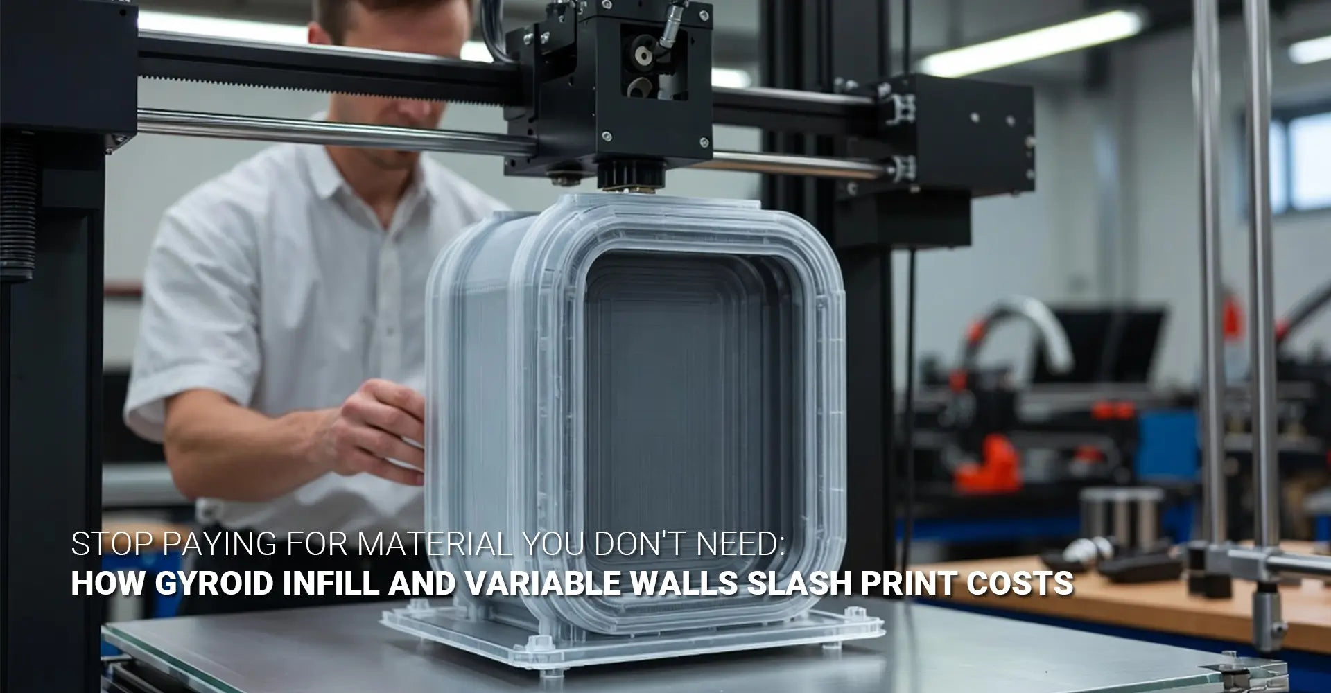
Most engineers never question the default settings. They send a file, get a quote, and pay the bill. But here's the uncomfortable truth: a huge portion of that bill may be paying for material that does absolutely nothing. No structural purpose. No functional benefit. Just dead weight — and wasted money. 3D printing cost reduction doesn't require a new machine or a new supplier. It starts with understanding what's actually inside your parts.
The Short Answer: How to Cut 3D Printing Costs by 40%
Stop using uniform infill and uniform walls. Start putting material only where stress demands it.
| Strategy | Potential Cost Impact | Complexity |
|---|---|---|
| Switch to gyroid infill at 20% density | Up to 25% savings | ⭐ Low |
| Apply variable wall thickness | Up to 20% savings | ⭐⭐ Medium |
| Combine both strategies | Up to 40% savings | ⭐⭐ Medium |
| Process-specific hollowing (SLS/SLA) | Up to 3× cheaper | ⭐⭐ Medium |
These aren't theoretical numbers. They're backed by real case data and industry benchmarks. And the best part? You don't need expensive new software to get started.
So where exactly is your money going — and how do you take it back? In this guide, we'll walk through the four key levers: understanding cost drivers, choosing the right infill pattern, finding the optimal density, and using gradient wall thickness to remove material you're paying for but don't need. By the end, you'll have a clear, actionable checklist to bring to your next 3D printing order.
Table of Contents
- Why Default Infill Settings Are Draining Your Budget
- Which Infill Pattern Actually Saves Money?
- How Low Can You Set Infill Density Before Your Part Fails?
- What Is Gradient Wall Thickness and How Does It Cut Cost Per Part?
- Conclusion
Why Are Default Infill Settings Quietly Draining Your 3D Printing Budget?
When you submit a part for 3D printing, the service provider typically uses default settings unless you specify otherwise. These defaults are designed to be "safe" — not economical. They assume you want maximum material, maximum strength, and minimal risk of failure. However, that assumption costs you real money on every single part.
The Three Hidden Cost Drivers
The key insight: In 3D printing, material volume and print time are directly linked. More material = longer prints = higher cost.
Here's how the costs stack up:
- Material volume — The direct line item. Every gram of filament, resin, or powder has a price. Uniform high-density infill fills your part with material that often serves zero structural purpose.
- Print time = machine time = money — A denser part takes longer to print. Longer print times mean higher machine costs, especially on industrial printers. Print time reduction is one of the fastest ways to lower your bill.
- The hidden multiplier — More material doesn't just cost more directly. It also increases print time, which multiplies the cost. A 30% material reduction can sometimes produce a 35%+ cost reduction when time savings are included.
The Math Behind Wasted Material
Let's make this concrete. Imagine a simple bracket printed at 50% uniform infill with 2mm walls throughout. Now imagine that 80% of that part never experiences meaningful stress during real-world use. You've just paid for material in those regions that contributes nothing. Multiply that across a production run of 100 parts, and the waste becomes significant.
For parts used in industrial machinery applications, where production volumes are higher and tolerances are tighter, this waste compounds quickly. The solution isn't to guess — it's to analyze where stress actually occurs, and only put material there.
Which Infill Pattern Actually Saves Money — And Does Gyroid Really Win?
Not all infill patterns are equal. Some are fast to print but weak in certain directions. Others are strong but slow. And one — gyroid — hits a sweet spot that makes it the clear winner for most cost-sensitive applications. Understanding the infill pattern comparison helps you make smarter design decisions from the start.
Infill Pattern Comparison at a Glance
Gyroid infill delivers near-isotropic strength at lower densities — meaning you can use less of it without sacrificing performance.
| Pattern | Strength Direction | Print Speed | Cost Efficiency |
|---|---|---|---|
| Rectilinear / Grid | Directional (weak at angles) | Fast | Low |
| Cubic | Better, still anisotropic | Medium | Medium |
| Gyroid | Near-isotropic (all directions) | Fast | High |
- Rectilinear and Grid — These are the default patterns in most slicers. They print fast, but they're directionally weak. Load them from an unexpected angle, and they fail sooner than expected.
- Cubic — An improvement over grid patterns. However, it's still anisotropic, meaning strength varies depending on load direction.
- Gyroid — Based on a triply periodic minimal surface, gyroid infill strength comes from its three-dimensional, self-intersecting structure. It performs consistently regardless of load direction. It also has no crossing paths mid-layer, so it actually prints faster than many complex patterns.

Research-Backed Efficiency at Lower Densities
Research consistently shows that gyroid maintains excellent mechanical performance even at densities as low as 15–20%. This is the key to cost savings. With rectilinear infill, dropping from 50% to 20% often creates unacceptable weak points. With gyroid, that same reduction is frequently safe — and even preferable. This makes gyroid infill strength the practical foundation of any serious cost-reduction strategy.
For automotive components and brackets where weight and cost both matter, gyroid at reduced density is increasingly the standard choice among experienced design engineers.
How Low Can You Set Infill Density Before Your Part Fails?
This is the question most engineers are afraid to ask. The answer, however, is more reassuring than you might think. Infill density optimization is not about pushing parts to failure — it's about understanding what each part actually needs, and matching material placement to real-world load conditions.
The Three-Tier Density Guide
The goal is simple: match your infill density to the actual job your part needs to do — nothing more.
Tier 1 — Visual and Aesthetic Parts
- Recommended density: 5–10% infill
- These parts carry no load and bear no stress.
- Examples: display models, prototypes for client presentations, enclosures with no mechanical load.
- Result: Maximum material savings with zero functional compromise.
Tier 2 — Functional, Non-Load-Bearing Parts
- Recommended density: 15–25% gyroid infill
- These parts need some rigidity and durability, but don't carry significant mechanical loads.
- Examples: cable holders, clips, guides, housings.
- Result: Strong enough for daily use, with significant material and cost savings.
Tier 3 — Load-Bearing Components
- Recommended density: Variable — high only at stress concentration points
- These parts genuinely need material — but not everywhere.
- Examples: structural brackets, jigs, fixtures, mechanical linkages.
- Result: Lightweight 3D printing design achieved by concentrating material where FEA shows it's needed.

Variable Density — The Right Way to Approach Load-Bearing Parts
For load-bearing components, the answer is never "use high infill everywhere." Instead, run a basic stress analysis (FEA). Identify where stress concentrates — typically at mounting holes, joints, and load transfer points. Apply high density only in those regions. Use 15–20% gyroid everywhere else. This approach is how professionals reduce material in 3D printing without compromising the parts that matter most.
If you're working with 3D printing plastics — such as PETG, ASA, or nylon — understanding material behavior under load becomes even more important, since different polymers respond differently to density reduction.
What Is Gradient Wall Thickness and How Does It Cut 3D Printing Cost Per Part?
Infill is only half the story. The other major cost driver is your part's shell — the walls. Most designers apply a uniform wall thickness throughout. It feels safe and simple. But it's also one of the biggest sources of unnecessary material cost. Variable wall thickness 3D printing is the advanced technique that changes this — and the savings can be dramatic.
The Core Principle: Material Follows Stress
Topology optimization additive manufacturing tells us one simple thing: put material where loads travel, remove it everywhere else.
Here's how it works in practice:
- Thicker walls at stress points — Mounting holes, load application points, and joint interfaces need robust walls. These regions should receive your maximum wall thickness (typically 3–4mm).
- Thinner walls everywhere else — Low-stress regions — flat faces, unsupported surfaces away from load paths — can safely use 1–1.5mm walls.
- The net result — You use significantly less material overall, with no measurable reduction in structural integrity under real operating conditions.
Real Example — 40% Savings on a Production Bracket
Here's the math that makes this real.
Case A — Default Design (Baseline):
- Infill: 50% uniform rectilinear
- Walls: 2mm uniform throughout
- Material volume: 100% (baseline)
- Print time: 100% (baseline)
- Cost: $100 per part
Case B — Optimized Design:
- Infill: 20% gyroid
- Walls: 3mm at mounting points, 1.2mm on low-stress faces
- Material volume: ~60% of baseline
- Print time: ~65% of baseline
- Cost: ~$60 per part
That's a 40% reduction in 3D printing cost per part — with no loss of function. Xometry's published data supports this, noting that hollow or optimized parts can be up to three times cheaper than their solid equivalents.
The volume multiplier: At 100 parts, that's $4,000 saved. At 1,000 parts, it's $40,000. The savings scale directly with production quantity.
This principle also applies across technologies. The SLA vs FDM cost saving opportunity differs by process:
| Process | Primary Cost Lever | Key Strategy |
|---|---|---|
| FDM | Infill density + pattern | Gyroid at 15–20% |
| SLS / MJF | Part volume and hollowing | Shell-only with drainage holes |
| SLA | Resin volume | Shell designs, minimal internal structure |
For parts requiring tight tolerances or specific surface finish requirements, discuss with your supplier which process gives you the best cost-to-quality ratio after optimization.
Conclusion
The Bottom Line
Cutting 3D printing costs by 40% is not about finding a cheaper supplier. It's about designing smarter parts. Here's the three-step action plan:
- Run a stress analysis — Identify where material is actually needed in your part. FEA doesn't need to be complex. Even a basic simulation reveals the critical zones.
- Apply infill and wall optimization — Switch to gyroid at 15–25% for most parts. Apply variable walls — thick at stress points, thin everywhere else. Use the three-tier density guide to match infill to function.
- Ask your supplier the right questions — Request DFM (Design for Manufacturability) feedback. Ask: "Where can we reduce infill or thin the walls without risking part performance?" A good manufacturing partner will tell you honestly.
Key Takeaways
- ✅ Default 3D printing settings are designed for safety, not economy
- ✅ Gyroid infill provides near-isotropic strength at densities as low as 15–20%
- ✅ Variable wall thickness removes material from low-stress regions without weakening parts
- ✅ Combining both strategies can deliver up to 40% cost reduction
- ✅ Savings scale with production volume — optimization pays off faster than you think
- ✅ Process choice matters: FDM, SLS, and SLA each have different primary cost levers
The engineers who win on cost aren't the ones with the cheapest supplier. They're the ones who send smarter files.
Recommended External Resources
[3D printing cost reduction][^1]
[Infill density optimization][^2]
[Gyroid infill strength][^3]
[Variable wall thickness 3D printing][^4]
[Reduce material 3D printing][^5]
[3D printing cost per part][^6]
[^1]: Peer-reviewed research demonstrating how infill density optimization directly reduces material costs and printing time in 3D printing, with specific findings on optimal settings for PLA materials [citation:5].
[^2]: Comprehensive methodology for optimizing FDM process parameters including infill density to minimize production costs while maintaining part quality, identifying optimal settings for cost-effective manufacturing [citation:8].
[^3]: Peer-reviewed research investigating the effective yield strength of gyroid infills through combined numerical and experimental approaches, developing semi-empirical relationships for strength as a function of relative density for design optimization workflows [citation:1].
[^4]: A novel slicing and path generation method enabling uniform wall thickness in periodic surface structures by generating adjacent implicit surfaces with consistent offset distance, eliminating STL discretization errors [citation:6].
[^5]: Fraunhofer IAPT research demonstrates how topology optimization and support structure minimization reduce material usage by 35% and total costs by 50% compared to conventional milling for automotive series production [citation:8].
[^6]: Karsan vehicle manufacturer case study showing 80% cost reduction per part set (from €2500 to €500) by transitioning from sheet metal to in-house FDM 3D printing for electric vehicle components [citation:6].

