Precision Die Casting Tolerances: Can You Really Hit ±0.1mm Right Out of the Mold?
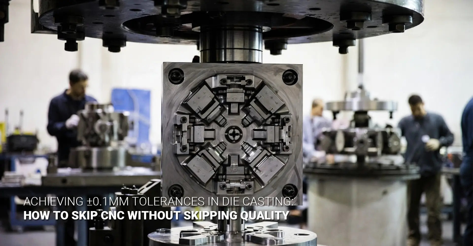
Precision Die Casting Tolerances: Can You Really Hit ±0.1mm Right Out of the Mold?

Most engineers have heard it before: "Die casting is great for volume — but you'll need to machine the critical dimensions." It sounds reasonable. After all, die casting involves heat, pressure, molten metal, and shrinkage. Surely that adds up to variation, right?
Not necessarily. The reality is more nuanced — and more exciting for engineers who care about cost and lead time.
Quick Answer: Yes. Precision die casting tolerances of ±0.1mm are achievable on specific features — bearing pockets, locating bosses, mounting surfaces — when three factors align: mold accuracy, clamping force consistency, and sliding core design. The right supplier, with the right process, can deliver as-cast precision components that go straight to assembly.
So how does it actually work? And where are the limits? This article breaks it all down — pillar by pillar — so you can decide whether precision die casting is the right call for your next project.
Table of Contents
- Why Do Engineers Assume Die Casting Can't Hold Tight Tolerances?
- What Makes Mold Accuracy the Foundation of Precision Die Casting?
- How Does Clamping Force Consistency Protect Dimensional Accuracy?
- What Role Do Precision Sliding Cores Play in Achieving ±0.1mm?
- Conclusion & Buyer Checklist
Why Do Engineers Assume Die Casting Can't Hold Tight Tolerances?
The assumption is understandable. Most engineers are trained on general process capability tables. For conventional die casting, those tables show tolerances in the range of ±0.25mm to ±0.5mm. So the mental model becomes: cast the shape, machine the precision.
But that model is based on average die casting — not on what's possible with deliberate process engineering. The gap between standard die casting and high precision die casting is not a matter of luck. It's a matter of investment and intent.
Snippet: Standard die casting tolerances typically fall between ±0.25mm and ±0.5mm for general dimensions. However, critical features on well-designed parts — using precision tooling and controlled processes — can consistently achieve the ±0.1mm die casting tolerance threshold, as-cast, without secondary machining.
GD&T Context: What "±0.1mm" Really Means on a Cast Part
When we talk about GD&T for die castings, the conversation gets more specific. Tolerances don't exist in a vacuum — they apply to particular features under particular GD&T callouts.
Here's the practical breakdown:
| GD&T Characteristic | As-Cast Achievability | Notes |
|---|---|---|
| True Position | ±0.1mm on boss/hole features | Achievable with precise core placement |
| Flatness | 0.05–0.15mm on datum pads | Depends on wall thickness and cooling |
| Parallelism | 0.1mm on mating faces | Requires platen parallelism in machine |
| Diameter / Bore | ±0.1mm on core-defined holes | Hydraulic cores with feedback required |
| Threads / Mirror Finish | Not reliably as-cast | Usually still requires post-processing |
The key rule: Features defined by the mold cavity or sliding cores are best positioned to hold net shape die casting tolerances. Features that cross the parting line, or depend on two halves of the mold aligning perfectly, carry more inherent risk.
So before assuming CNC is unavoidable, ask: which specific dimensions need tight control, and where do they sit in the mold? That question changes everything.
What Makes Mold Accuracy the Foundation of Precision Die Casting?
If there's one principle that separates a precision die caster from a standard one, it's this: the mold is the part. Every dimension on the finished casting is a reflection of the mold cavity. If the mold is off, the part is off — and no amount of process tweaking downstream will fix a fundamentally inaccurate tool.
This is why mold accuracy die casting is the first — and most critical — pillar of tight tolerance casting. It's also why precision tooling costs more. That premium isn't markup. It's engineering.
Snippet: Achieving ±0.1mm as-cast tolerances starts with mold cavities machined to within ±0.02mm of nominal. This requires premium tool steel, 5-axis CNC cavity machining, and thermal management systems that ensure the mold behaves the same way on shot 1 as it does on shot 50,000.

The Three Hardware Investments That Make It Possible
1. Premium Tool Steel Selection
Standard die casting tools often use H13 tool steel — a solid, workable choice. But for tight tolerance work, suppliers may upgrade to higher-grade variants with tighter grain structure and better thermal fatigue resistance. The goal is die casting dimensional stability across hundreds of thousands of cycles. A mold that changes shape as it heats up and wears will produce parts that drift out of tolerance. Better steel reduces that drift.
2. 5-Axis CNC Machining of Cavities
General mold machining uses 3-axis equipment — adequate for most work, but it introduces limitations on complex surfaces. Precision die casting molds use 5-axis CNC machining, which allows the cutter to approach the surface from multiple angles without re-fixturing. The result is:
- Fewer setup errors from multiple fixtures
- Tighter surface contour accuracy on curved or angled features
- Better surface finish straight off the machine, reducing hand-polishing that introduces human error
3. Conformal Cooling for Uniform Shrinkage
Shrinkage is the reason most people assume die casting can't be precise. Metal shrinks as it solidifies — and if different sections of the part cool at different rates, you get uneven shrinkage and warped dimensions.
Conformal cooling channels follow the contour of the mold cavity, keeping thermal gradients uniform. When the whole part cools at the same rate, shrinkage becomes predictable and repeatable rather than random. That predictability is what allows the mold maker to compensate for shrinkage in the tool design — and deliver parts that hit nominal dimensions consistently.
For engineers specifying precision die cast components, understanding what goes into the tooling decision helps you ask better questions of your supplier — and evaluate their quotes more critically.
How Does Clamping Force Consistency Protect Dimensional Accuracy?
Here's a failure mode that doesn't get enough attention: die separation during injection. It's subtle. It's often not visible to the naked eye on individual parts. But it's one of the fastest ways to destroy dimensional accuracy at scale.
During the injection phase, molten metal is forced into the mold cavity at high pressure — often 600–1,200 bar. If the clamping force holding the two halves of the die together isn't sufficient, or isn't consistent, the die separates microscopically. Metal flows into that gap. Flash forms. And the part moves.
Clamping force consistency isn't just a machine spec. It's a precision control variable.
Snippet: Inconsistent clamping force allows die separation during injection, producing flash and part movement that directly destroys dimensional accuracy. Precision die casting machines maintain consistent tonnage throughout every shot, with tie bar load leveling to ensure platen parallelism — protecting die casting process capability on critical features.
Three Mechanisms That Maintain Clamping Precision
1. Real-Time Clamp Force Monitoring
Modern precision die casting machines don't just set clamp force — they monitor it continuously. Sensors on the tie bars measure actual load during every shot. If the force drifts due to thermal expansion of the machine frame or tool wear, the system detects it and compensates. This keeps every shot operating within the same parameters — which is the definition of process control.
2. Tie Bar Load Leveling for Platen Parallelism
A four-tie-bar machine applies clamping force through four points. If those four points aren't applying equal force, the platen tilts slightly. A tilted platen means the two mold halves aren't perfectly parallel — and even a fraction of a degree of tilt introduces measurable variation into parting-line dimensions.
Tie bar load leveling ensures all four bars carry equal load. The platens stay parallel. The parting line stays where it's supposed to be.
3. Shot Profile Repeatability
Clamping and injection aren't independent variables — they interact. A consistent shot profile (fill speed, intensification pressure, timing) combined with consistent clamping produces the same fill pattern, the same pressure distribution, and the same solidification behavior on every cycle. This shot-to-shot repeatability is what enables long-run industrial machinery components to hold tolerance across tens of thousands of parts, not just the first few off the tool.
What Role Do Precision Sliding Cores Play in Achieving ±0.1mm?
For many engineers, this is the piece that completes the picture. Mold accuracy and clamping consistency address features defined by the main cavity halves. But what about holes perpendicular to the draw direction? Undercuts? Internal passages? Side-wall features?
Without sliding cores, those features require post-cast drilling, milling, or reaming. With sliding core design die casting — done properly — many of those features can be produced as-cast, to ±0.1mm, with no secondary operation required.
That's the real promise of precision die casting. It's not just about holding the tolerance you'd get from machining. It's about eliminating the machining in the first place — and the lead time, cost, and scheduling overhead that goes with it.
Snippet: Hydraulically actuated sliding cores with position feedback can hold ±0.1mm on features — bore diameters, slot widths, hole positions — that would traditionally require CNC drilling or milling after casting. This is how precision die casting directly reduces CNC machining die casting costs and cycle times at scale.
How Sliding Cores Deliver Precision
1. Hydraulic Core Pulls with Position Feedback
The precision difference between a basic sliding core and a precision one comes down to actuation and feedback. Basic cores use mechanical cams driven by die opening — simple, but with inherent positional variation. Precision cores use hydraulic actuation with closed-loop position feedback. A sensor confirms the core is in exact position before injection begins. If it's off, the machine holds. No part is made until the core is where it needs to be.
This is how bore diameters and hole positions achieve the kind of repeatability associated with machined features — without a single CNC operation.
2. Zero-Draft Possibilities on Core-Defined Features
Draft angles exist to allow parts to release from the mold. On surfaces defined by the main cavity, some draft is usually required. But on features defined by a sliding core — where the core pulls away from the feature rather than the part pulling away from the core — zero draft is achievable. That means straight-walled bores, flat-bottomed pockets, and parallel slot walls, all as-cast.
For automotive components where bore geometry directly affects function — bearing fits, seal grooves, fluid passages — this matters enormously.
3. Sequential Action Timing for Complex Geometries
Some parts require multiple cores acting in sequence — one core retracting before another advances, for example, to avoid interference on complex internal geometries. Precision die casting machines control this sequencing with millisecond timing. The result is consistent, repeatable geometry on parts that would otherwise be considered too complex for as-cast precision.
This is also where surface finish quality intersects with dimensional precision — because a well-controlled core pull produces a cleaner surface that may not require any additional finishing, further compressing the overall production process.
Conclusion & Buyer Checklist
What We've Covered
Precision die casting is real — but it's not automatic. It requires three pillars working together:
- Mold accuracy — cavities machined to ±0.02mm, premium steel, conformal cooling
- Clamping force consistency — real-time monitoring, tie bar leveling, shot repeatability
- Sliding core precision — hydraulic actuation, position feedback, zero-draft capability
When all three are in place, tight tolerance casting at ±0.1mm on critical features is not a stretch goal. It's a repeatable, documentable outcome.
The Cost Reality
Expect precision tooling to cost 30–50% more than standard die casting tooling. That premium covers:
- Higher-grade tool steel
- 5-axis cavity machining
- Conformal cooling design
- Hydraulic core systems and sensors
- Extended validation and tryout cycles
The payback comes from eliminating 3–5 CNC operations per part. For volumes above 5,000–10,000 parts, the math almost always favors precision tooling. Lower per-part cost. Shorter lead time. No secondary operation scheduling.
Your Precision Die Casting Supplier Checklist
Before committing to a supplier claiming ±0.1mm capability, ask for the following:
- [ ] Cpk values ≥ 1.33 on critical dimensions from a similar part
- [ ] First article inspection reports showing actual as-cast measurements vs. nominal
- [ ] Process monitoring data from production runs (shot profile, clamp force logs)
- [ ] References from customers with similar precision requirements
- [ ] Tooling capability documentation — steel grade, machining equipment, cooling design
A supplier who can deliver precision will have this data ready. One who can't will give you promises instead.
Design-Side Takeaway
The parts that hit ±0.1mm as-cast are designed for it from the start. That means:
- Specifying which dimensions truly need tight control
- Positioning critical features on the parting line or core-defined surfaces
- Allowing realistic draft where precision isn't required
- Engaging your die caster during design — not after the drawing is finalized
Precision die casting doesn't happen to a part. It's built into a part — from the first line on the drawing.
External Links & Further Reading
[Precision die casting tolerances][^1]
[high precision die casting][^2]
[net shape die casting tolerances][^3]
[±0.1mm die casting tolerance][^4]
[die casting dimensional stability][^5]
[mold accuracy die casting][^6]
[^1]. This article provides an introduction to precision die casting, focusing on frequently asked questions including the tightest tolerances achievable for zinc and aluminum, and the factors influencing these tolerances.
[^2].This article details the advantages and disadvantages of high-pressure die casting, emphasizing its precision, speed, and cost-effectiveness for creating aluminum or zinc components with specific dimensional tolerances.
[^3]. This technical document outlines the NADCA product specification standards for die casting, detailing how net-shape components can be achieved through improved dimensional accuracy and stability.
[^4].This knowledge hub article discusses small-batch die casting capabilities, highlighting the ability to achieve high repeatability with precision casting tolerances of ±0.1 mm or better for complex, thin-walled geometries.
[^5]. This blog post from General Die Casters explores the critical factors affecting the dimensional stability of high-pressure die castings, such as casting solidification, die temperature variability, and process control parameters.
[^6]. This knowledge hub article from Neway explains how in-depth mold flow analysis and precise mold geometries are essential for achieving high dimensional accuracy and preventing defects in the die casting process.


