How Can You Achieve Uniform Coatings on Complex Part Surfaces?
How Can You Achieve Uniform Coatings on Complex Part Surfaces?

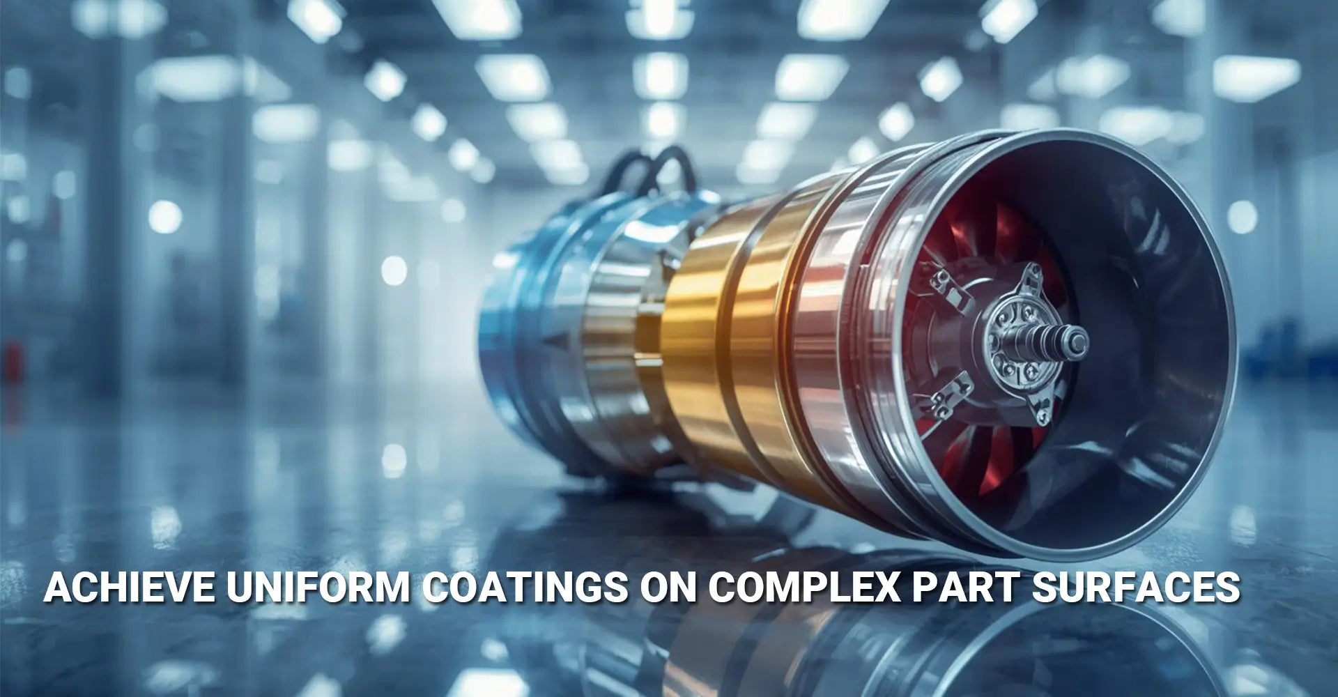
Getting an even coating on complex parts feels like solving a puzzle. Moreover, manufacturers face constant challenges when trying to coat intricate geometries with consistent thickness. Whether you're working with aerospace components, medical devices, or custom CNC machined parts, achieving complex part surface coating uniformity directly impacts product quality and performance. Additionally, uneven coatings lead to premature wear, corrosion failures, and costly rejections. Therefore, understanding the science behind coating distribution becomes essential for anyone serious about quality manufacturing.
Quick Reference: Common Coating Problems & Solutions
| Common Coating Problems | Root Causes | Quick Solutions |
|---|---|---|
| Edge buildup | Current density concentration | Fixture rotation + auxiliary anodes |
| Thin coverage in recesses | Line-of-sight limitations | CVD or optimized PVD angles |
| Color variation | Uneven deposition rates | Process parameter adjustment |
| Poor adhesion | Surface contamination | Ultrasonic cleaning + activation |
Now that you've seen the main challenges, let's dive into practical solutions. Furthermore, understanding the physics behind these coating issues helps you choose the right techniques for your specific application. Consequently, you'll save time and money by avoiding trial-and-error approaches. In this guide, we'll explore proven strategies that manufacturers use to achieve consistent coatings on even the most challenging part geometries.
Table of Contents
- Why Do Complex Geometries Create Uneven Coating Thickness?
- What Fixture Design Strategies Guarantee Better Coating Distribution?
- How Do CVD and PVD Technologies Handle Non-Line-of-Sight Areas?
- Which Electroplating Adjustments Control Thickness Variation?
Why Do Complex Geometries Create Uneven Coating Thickness?
Understanding the physics behind coating problems helps you fix them faster. When you coat parts with sharp edges, deep holes, or unusual shapes, several forces work against you. Therefore, knowing these challenges lets you plan better solutions.
The Main Causes of Uneven Coating
Complex parts create coating problems through several mechanisms. First, shadowing effects happen in line-of-sight processes when one part of the geometry blocks material from reaching another area. Second, current density differences in electroplating cause some areas to attract more coating material than others. Third, gas flow restrictions in vapor deposition prevent uniform coverage in tight spaces. Finally, how you position the part during coating dramatically affects the final result.
The Physics Behind Coating Non-Uniformity
Electric fields behave differently around complex shapes during electroplating. Specifically, sharp edges and corners concentrate electric field lines, which pulls more metal ions to these areas. Meanwhile, recessed surfaces receive fewer field lines and therefore get thinner coatings. This phenomenon explains why corners often show thick buildup while holes remain undercoated.
Similarly, PVD processes face geometric challenges because coating atoms travel in straight lines. When atoms leave the target source, they hit surfaces facing the source first. However, sidewalls and internal features receive fewer particles because of their angle. Research shows that a 90-degree surface relative to the source receives only 50% of the coating thickness compared to a perpendicular surface.
Additionally, non-line-of-sight coating challenges become severe when dealing with industrial machinery components that have complex internal passages. Gas molecules in CVD can navigate around corners, but physical vapor atoms cannot. Therefore, part designers must consider coating requirements during the initial design phase to avoid impossible-to-coat features.
What Fixture Design Strategies Guarantee Better Coating Distribution?
Your fixture design directly determines coating success or failure. Moreover, smart fixture engineering solves many uniformity problems without changing the coating process itself. Therefore, investing time in fixture design for coating uniformity pays immediate dividends.
Key Fixture Design Principles
Successful fixtures share several common features. Multi-axis rotation systems continuously change the part's orientation relative to the coating source, which averages out thickness variations. Custom holders designed for specific geometries ensure optimal positioning throughout the process. Additionally, where you place conductive contact points affects current distribution in electroplating, so strategic placement prevents shadowing and ensures good electrical connection. Finally, proper spacing between multiple parts prevents them from blocking each other during coating.

Advanced Fixture Techniques That Work
Professional coating shops use sophisticated fixture strategies to handle difficult parts. Planetary rotation mechanisms spin parts around their own axis while simultaneously orbiting around the coating source. This double rotation ensures every surface angle receives equal exposure to coating material.
Furthermore, adjustable angle mounts let operators tilt parts during the process to reach stubborn areas. Calculating optimal rotation speeds requires balancing deposition rate with mechanical limitations. Generally, faster rotation improves uniformity, but excessive speed can cause part vibration or fixture failure.
Case studies demonstrate impressive results from fixture optimization. One aerospace manufacturer redesigned fixtures for turbine blade coating and improved thickness uniformity by 62%. Another company coating medical implants reduced rejection rates from 18% to under 3% simply by implementing calculated rotation speeds.
When working with metals and plastics, fixture material selection matters too. Conductive fixtures work best for electroplating, while thermally stable materials suit high-temperature CVD processes. Therefore, matching fixture materials to your coating method prevents contamination and ensures repeatable results.
How Do CVD and PVD Technologies Handle Non-Line-of-Sight Areas?
Different coating technologies offer distinct advantages for complex geometries. Specifically, understanding PVD CVD coating uniformity differences helps you select the right process for your application.
Technology Comparison for Complex Parts
| Technology | Step Coverage | Best Applications | Limitations |
|---|---|---|---|
| CVD | Excellent - gas-phase deposition reaches all surfaces | Deep holes, internal channels, complex cavities | Higher process temperatures, slower deposition |
| Standard PVD | Poor - requires direct line-of-sight | Flat surfaces, simple geometries | Cannot coat hidden features |
| Ionized PVD | Good - charged particles follow electric fields | Moderate complexity parts, controlled coverage | More expensive equipment |

Technical Breakdown of Conformal Coating Methods
CVD achieves remarkable uniform coating on complex geometries through chemical reactions rather than physical deposition. Gas molecules flow into every cavity and crack, then chemical reactions cause coating material to deposit atom-by-atom on all exposed surfaces. This process naturally creates conformal coatings that follow surface contours precisely.
For example, coating the inside of a 0.5mm diameter hole presents no challenge for CVD because gas molecules easily diffuse into the space. The coating thickness inside the hole matches the exterior thickness within 5-10%. However, traditional PVD would leave the hole interior completely uncoated.
Plasma-enhanced CVD (PECVD) offers additional benefits by using electric fields to direct reactive species. This enhancement allows lower process temperatures while maintaining excellent step coverage. Medical device manufacturers particularly value PECVD for coating temperature-sensitive materials.
Meanwhile, ionized PVD variants improve upon standard sputtering by charging deposited particles. These charged atoms respond to electric fields applied around the part, which steers them toward shadowed areas. Although ionized PVD doesn't match CVD's conformal ability, it significantly outperforms conventional sputtering on moderately complex parts.
Hybrid approaches combine technologies strategically. Some manufacturers apply PVD for the base layer where its superior density and adhesion excel, then use CVD for the topcoat to ensure complete coverage. This combination delivers both performance and uniformity.
When selecting surface finish processes, consider that CVD typically produces matte finishes while PVD can create mirror-like surfaces. Therefore, your aesthetic requirements may influence technology selection alongside technical coating needs.
Which Electroplating Adjustments Control Thickness Variation?
Electroplating offers tremendous flexibility for achieving uniform coatings through parameter adjustment. Moreover, electroplating thickness control becomes precise once you understand the critical variables affecting deposition distribution.
Critical Parameters to Adjust
Several factors control where metal deposits during electroplating. Bath composition and additives fundamentally affect how ions behave in solution. Leveling agents slow deposition at high-current-density areas, while brighteners improve surface finish. Current density profiles determine deposition rate, with higher density causing faster plating. The anode-cathode configuration shapes the electric field that drives deposition. Pulse plating versus direct current changes how ions approach the surface. Finally, solution agitation methods ensure fresh ions constantly reach all part surfaces.
Mastering Electroplating Uniformity
Leveling agents work through fascinating chemistry. These molecules preferentially adsorb onto high-current-density areas like edges and corners. Once adsorbed, they temporarily block metal deposition at those spots. Consequently, ions deposit preferentially in lower-current areas, which evens out the coating thickness. The most effective leveling agents release from the surface after a few seconds, allowing continued deposition.
Auxiliary anode placement strategically adds current sources near recessed areas. For instance, when plating a deep cavity, placing a small auxiliary anode near the cavity opening directs current flow inward. This technique requires careful calculation because improper auxiliary anode positioning can worsen rather than improve uniformity.
Pulse plating offers significant advantages over direct current for complex geometries. During pulse plating, current alternates between high levels and zero. The "on" period deposits metal rapidly, while the "off" period lets ions diffuse into recessed areas and leveling agents redistribute. Research demonstrates that optimized pulse parameters improve thickness uniformity by 30-50% compared to DC plating.
Computational models have transformed electroplating optimization. Finite element analysis (FEM) software predicts current density distribution based on part geometry, anode positions, and bath conductivity. Engineers input a 3D model of their part, and the software generates thickness distribution maps. This capability slashes development time because you can virtually test different configurations before physical trials.
One automotive supplier used FEM modeling to optimize plating of complex bracket assemblies. The simulation revealed that moving the anode 15cm closer and adding two auxiliary anodes would improve uniformity by 45%. Physical testing confirmed the prediction, and the company implemented the changes across three production lines. The result was a 68% reduction in scrap rates and $240,000 annual savings.
When implementing edge effect coating solutions, remember that multiple small adjustments often work better than single large changes. Start by optimizing bath chemistry with appropriate leveling agents. Next, evaluate anode positioning and add auxiliaries where needed. Then test pulse plating parameters. Finally, verify results with thickness measurements and iterate.
Conclusion
Achieving uniform coatings on complex parts requires combining technical knowledge with practical process control. Throughout this guide, we've explored how physics creates coating challenges and which proven solutions overcome them.
Key Takeaways for Better Coating Uniformity
The path to consistent coatings starts with understanding why problems occur. Physics governs how coating materials deposit, and complex geometries create inherent challenges. However, smart strategies overcome these obstacles.
First, proper fixture design makes an immediate impact. Rotating parts during coating averages out thickness variations and ensures all surfaces receive equal exposure. Second, selecting the right coating technology matters tremendously. CVD excels at conformal coverage in tight spaces, while PVD offers superior density and adhesion on simpler geometries. Third, electroplating parameter optimization provides fine control over thickness distribution.
Most importantly, combining multiple strategies delivers the best results. A manufacturer coating surgical instruments might use optimized fixtures, pulse plating with leveling agents, and FEM modeling to predict results. This comprehensive approach consistently produces coatings within ±5% thickness tolerance.
Start your improvement journey with substrate preparation and fixture evaluation. These changes require minimal investment but deliver substantial benefits. Clean surfaces ensure good adhesion, while thoughtful fixtures prevent most uniformity problems. Next, explore advanced techniques like pulse plating or ionized PVD for additional gains.
Remember that investing time in upfront planning dramatically reduces costly rework and scrap rates. Modeling your coating process virtually or testing small batches with different parameters saves money compared to full-production failures. Additionally, measuring coating thickness at multiple locations provides data for continuous improvement.
[External Links Recommendation]
[Complex part surface coating uniformity][^1]
[Edge effect coating solutions][^2]
[Uniform coating on complex geometries][^3]
[PVD CVD coating uniformity][^4]
[Electroplating thickness control][^5]
[Fixture design for coating uniformity][^6]
---
[^1]: Understanding best practices can enhance your coating processes, ensuring high-quality finishes and improved product performance.
[^2]: Exploring effective solutions can help mitigate edge effects, leading to better coating results and reduced waste in production.
[^3]: Exploring this resource will provide insights into advanced techniques and technologies for achieving uniform coatings on intricate shapes.
[^4]: This link will help you understand the differences and applications of PVD and CVD processes in achieving uniform coatings.
[^5]: Understanding best practices in electroplating thickness control can enhance your coating quality and efficiency.
[^6]: Exploring fixture design can help you achieve more consistent and uniform coatings, improving overall product quality.


