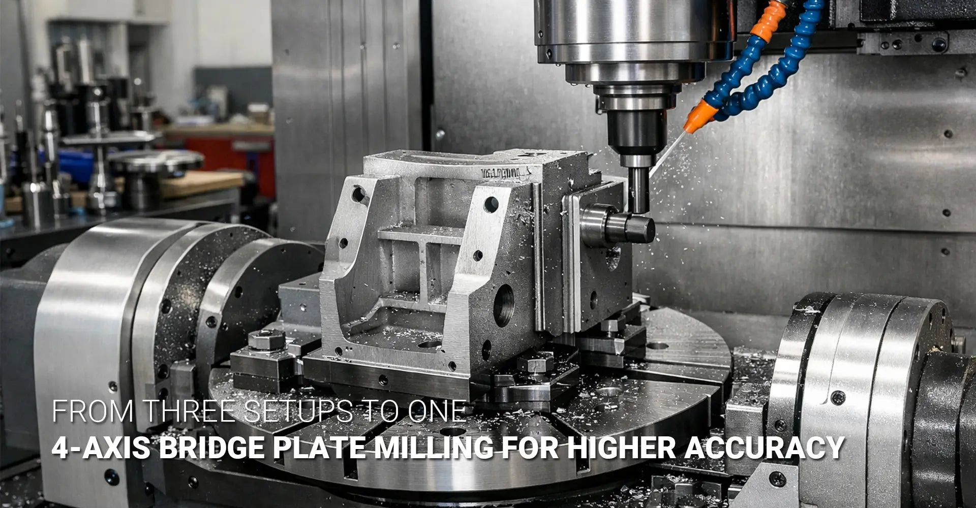
How Does 4-Axis CNC Milling Cut Costs While Improving Accuracy on Bridge Plates?
How Does 4-Axis CNC Milling Cut Costs While Improving Accuracy on Bridge Plates?

Many machine shops face a common headache when working with bridge plates and block-type components. You clamp the part, mill the first side, then flip it. You re-indicate, chase your datums, and hope everything lines up. After four separate setups, you finally have a finished part—but the holes don't quite align, faces show tiny steps where toolpaths meet, and you've burned hours on setups alone. This cycle wastes time, invites errors, and drives up costs on every job.
Quick Answer
4-axis CNC milling allows you to machine four sides of a bridge plate in one setup by using a rotary table. This eliminates three re-clamping steps, cuts cumulative tolerance by up to 70%, and reduces total machining time by 30-40% on complex multi-face parts—even though 4-axis machine rates run higher per hour. By holding a single master datum throughout the job, you avoid the datum errors that pile up with each re-clamp, delivering tighter tolerances and faster throughput on parts that demand precision across multiple faces.
The difference between traditional 3-axis work and 4 axis CNC one hit machining comes down to how you handle setups and datums. When you flip a part three or four times on a 3-axis mill, each new setup introduces small positioning errors. Those errors stack, and suddenly your tight-tolerance bridge plate is out of spec. A rotary table changes the game by letting you index the workpiece without ever breaking the original datum reference. The result is cleaner alignment between faces, fewer operator touches, and a finished part that meets print the first time. For shops running custom CNC milling services, understanding when and how to deploy 4-axis capability can be the difference between profit and rework.
Table of Contents
1. Why Do 3-Axis Multi-Setup Jobs Create Hidden Costs and Tolerance Problems?
2. What Does a 4-Axis Rotary Table Actually Add to Your Milling Capability?
3. How Does One-Hit Machining Work on Four Sides of a Bridge Plate?
4. When Does 4-Axis CNC Milling Actually Save Money Compared to 3-Axis?
5. Conclusion
Why Do 3-Axis Multi-Setup Jobs Create Hidden Costs and Tolerance Problems?
Picture a typical workflow for a bridge plate on a standard 3-axis mill. You start by clamping the raw stock in a vise, zeroing your work offset, and milling the top face. Then you flip the part 180 degrees, re-indicate the edges, establish a new datum, and machine the bottom. Next, you rotate the part 90 degrees to access a third side, repeat the indicating process, and cut those features. Finally, you flip it one more time for the fourth face. Each of these moves requires careful setup, and each one takes 15 to 25 minutes of operator time—time you can't bill as cutting.
Key Takeaway
Every time you re-clamp a part, you introduce 0.001"–0.003" of datum error. Across four setups, those errors stack—meaning your final hole position or face parallelism can drift by 0.005" or more, even when each individual setup was "good." This phenomenon, known as cumulative tolerance in multi setup machining, turns tight-tolerance jobs into high-risk gambles.
Understanding cumulative tolerance starts with understanding datums. A datum is the reference point or surface from which all measurements are made. In a single setup, your part sits in the vise, you touch off on a corner or edge, and the CNC control uses that zero as the origin for all toolpaths. As long as the part stays clamped, every feature you cut relates directly to that origin with high precision.
However, the moment you remove the part and re-clamp it, you must establish a new datum. Even with careful edge-finding and dial indicators, small errors creep in. The vise jaws may not grip exactly the same way, the part may rotate a fraction of a degree, or the operator may touch off 0.0015" off from the ideal location. Individually, these errors seem trivial, but they add up. If you have features on the first face that must align with features on the fourth face—such as a hole pattern that crosses multiple sides—the cumulative tolerance in multi setup machining can push you out of spec.
Beyond tolerance stack, multi-setup work burns time. A typical four-setup job might spend 60 to 100 minutes just on setups, not counting actual cutting. That's an hour or more of non-productive labor per part. For production runs, this setup overhead multiplies fast. Additionally, each setup carries scrap risk. If the operator mis-indicates a feature or the part shifts during clamping, you may cut a hole in the wrong place or leave extra stock on a critical face. By the time you discover the error, the part is already ruined.
For shops handling automotive or industrial machinery components, where bridge plates and structural blocks are common, these hidden costs and quality risks become major pain points. The question then becomes: how do you break this cycle?
What Does a 4-Axis Rotary Table Actually Add to Your Milling Capability?
A 4-axis mill adds a rotary axis—commonly called the A-axis or B-axis—to the standard X, Y, and Z linear axes. In practice, this rotary axis is usually a table that can spin the workpiece to any angle, letting the spindle access multiple faces without requiring the operator to physically move the part. This setup is often called "3+1" or "indexed 4-axis" because the rotary axis indexes to fixed positions (0°, 90°, 180°, 270°, etc.) rather than cutting continuously while rotating.
Key Takeaway
A rotary table lets you clamp the part once and rotate it to expose different faces—no operator intervention, no new vise jaw contact, and no new datum establishment. All four sides stay referenced to the same master datum throughout the job. This is the core advantage of 4 axis rotary table utilization: you preserve dimensional relationships across all faces because nothing ever moves relative to the original zero point.

When you mount a part on a rotary table, you're no longer relying on vise jaws to hold it in place for every operation. Instead, you use a custom fixture that bolts directly to the rotary table. This fixture is designed specifically for your part geometry, ensuring rigid, repeatable clamping that doesn't shift when the table rotates. Precision fixturing for 4 axis milling is critical because the fixture must remain stiff and balanced in every index position. If the fixture flexes or the part wobbles, you lose the accuracy gains that make 4-axis worthwhile.
Designing a good 4-axis fixture starts with understanding the part's critical datums. You choose one face or edge as the master datum—often a machined surface on the raw stock or a dowel pin hole—and mount the fixture so that datum aligns perfectly with the rotary axis center. Then, in your CAM software, you establish work offsets for each rotary position, all referenced back to that single master datum. This way, when the table indexes from 0° to 90°, the CNC control knows exactly where the new face is located in 3D space, and the toolpaths automatically adjust.
The 4 axis CNC milling cost per hour is typically higher than 3-axis work because the machines are more complex and the programming takes a bit more effort. However, the total job cost often drops because you eliminate three setups, reduce scrap, and improve throughput. Additionally, you free up your 3-axis machines for simpler jobs, making better use of your entire CNC machining service capacity.
Fixtures for rotary work also need clearance. The part can't collide with the table, the machine's column, or the spindle head as it rotates. This means the fixture must be compact and well-balanced. If the part hangs too far off one side, the centrifugal force during rotation can cause vibration or even damage the rotary motor. Good 4 axis CNC fixture design balances these mechanical constraints with the need for rigid clamping and easy part loading.
How Does One-Hit Machining Work on Four Sides of a Bridge Plate?
One-hit machining is exactly what it sounds like: you load the raw stock, clamp it once, and machine all required features in a single continuous setup. For a bridge plate with features on four sides, this means programming the CNC to cut the top, bottom, and two ends without ever stopping to re-clamp the part. The rotary table handles all the re-positioning, and the controller manages the work offsets for each indexed face.
Key Takeaway
In one-hit machining, you define a master datum once—usually the fixture mounting face and a dowel pin location. The CAM software then calculates toolpaths for each rotary index position, all referenced back to that single datum, so every hole and pocket on all four faces aligns perfectly. This approach eliminates the datum drift that plagues multi-setup jobs.
Here's how a typical multi side machining in one setup workflow unfolds. First, you mount the raw stock in the 4-axis fixture and secure it with clamps or bolts. Next, you touch off on the master datum—often a machined face or a dowel pin hole that you drilled in a preliminary step. This becomes your G54 work offset, the universal zero point for the entire job.
Then, in your CAM software, you create four work offsets (G54, G55, G56, G57, for example), each corresponding to a different rotary position. G54 might be the 0° position (top face), G55 the 90° position (first end), G56 the 180° position (bottom face), and G57 the 270° position (second end). Each offset shares the same origin point in space, but the coordinate system is rotated to match the new face orientation. This way, you can design your toolpaths as if you're always looking straight down at the part, even though the rotary table is spinning it around.
Programming proceeds face by face. For the top face, you might mill pockets, drill holes, and chamfer edges. Then you command the rotary table to index to 90°, switch to the G55 work offset, and machine the first end—perhaps drilling cross holes or milling a slot. The table indexes to 180°, you switch to G56, and machine the bottom face. Finally, it indexes to 270°, you switch to G57, and finish the second end. Throughout this entire sequence, the part never leaves the fixture, and every feature is referenced to the same master datum.
Tool length becomes more important in 4-axis work because the spindle may be cutting at odd angles relative to the part. You need to ensure your tool length offsets are accurate and that your tools are long enough to reach all features without colliding with the fixture or the rotary table. Collision detection in your CAM software is essential. Many modern CAM packages include simulation tools that show the entire machine envelope, the fixture, and the part rotating through all index positions. This lets you catch potential crashes before they happen on the real machine.
Cycle time improvements from bridge plate 4 side milling in one hit are significant. By eliminating three setups, you cut out 45 to 75 minutes of non-productive time per part. Even though you may spend a few extra minutes on each indexed operation (because 4-axis machines often run slightly slower to maintain accuracy during rotation), the net effect is a 30-40% reduction in total job time. Quality improves as well. Parallelism between opposing faces can be held to within 0.0005" because both faces are machined from the same datum in the same setup. Hole patterns that cross multiple faces line up perfectly, and you no longer see tiny steps or mismatches where toolpaths meet at the edges.
When Does 4-Axis CNC Milling Actually Save Money Compared to 3-Axis?
The economics of 4-axis work aren't always straightforward. A 4-axis machine costs more to buy, costs more to run per hour, and requires more sophisticated fixturing. So when does the investment pay off? The answer depends on part complexity, tolerance requirements, production volume, and setup time.
Key Takeaway
4-axis pays off when setup time dominates total job time, when tight tolerances between faces are critical, or when batch sizes justify fixture investment. For a typical bridge plate running 50+ pieces, eliminating three setups per part usually saves 20-35% in total labor and reduces scrap by half. The key is to reduce setup time in CNC milling by moving work from manual re-clamping to automated indexing.
Consider the difference between machine hours and operator hours. On a 3-axis mill, every setup requires hands-on operator time: loading the part, indicating the datums, running the first part to check dimensions, and adjusting offsets if needed. This operator involvement is expensive. In contrast, a 4-axis job may require the same or even slightly more machine time (because indexed moves and rotary positioning take a few extra seconds), but it drastically cuts operator time. Once the fixture is set and the program is proven, the operator simply loads raw stock and unloads finished parts. The machine does the rest.
For jobs where the part spends 10 minutes cutting and 60 minutes in setups, 4-axis delivers a massive advantage. For jobs where the part spends 2 hours cutting and only 10 minutes in setup, the benefit is smaller—though still real if tolerance is the issue. This is why 4 axis CNC milling cost analysis must consider both time and quality. Even if the hourly rate is higher, the total cost may be lower because you avoid scrap, rework, and excessive labor.
Fixture investment is another factor. A custom 4-axis fixture might cost $2,000 to $5,000 to design and build, depending on complexity. For a one-off prototype, that's hard to justify. For a production run of 100 parts, the fixture cost adds $20 to $50 per part—a reasonable premium if it saves $100 per part in labor and scrap. For a recurring production job, the fixture amortizes over thousands of parts, making the per-part cost negligible.
There are also cases where 3-axis work is still the right choice. Simple two-sided parts with loose tolerances don't benefit much from 4-axis. If you can hold your tolerances easily with standard vise work and the part only needs features on two faces, a rotary table just adds complexity without delivering value. Similarly, low-volume custom work may not justify the fixture investment. In these situations, CNC workholding for 4 axis rotary becomes an unnecessary expense, and a simple vise setup is faster and cheaper.
The decision framework is straightforward: audit your current multi-setup jobs, identify parts with tight inter-face tolerances or high setup-to-cut time ratios, and calculate the savings from eliminating setups. If you're running CNC metals plastics materials that machine quickly, the setup time penalty is even more painful, making 4-axis an even better fit. Conversely, if you're cutting slow, difficult materials where cycle time dominates, the setup savings matter less.
Conclusion
4-axis CNC milling delivers three core benefits: setup reduction, cumulative tolerance elimination, and throughput gains. By moving from four setups to one, you cut non-productive labor by 60-75% and remove the datum errors that cause parts to drift out of spec. By holding a single master datum throughout the job, you achieve tighter parallelism, better hole alignment, and cleaner transitions between faces. And by automating the indexing process, you speed up cycle times by 30-40% on qualifying parts.
However, 4-axis isn't a universal solution. It works best for multi-face bridge plates, block-type components, and structural parts where tight tolerances between faces are critical. It shines in production environments where batch sizes justify fixture investment and where setup time is a major cost driver. For simple two-sided work or low-volume custom jobs, traditional 3-axis vise setups may still be the most practical choice.
If you're struggling with tolerance stack on multi-setup jobs, spending hours on manual re-clamping, or scrapping parts because features don't align, it's time to audit your current workload. Identify the parts that would benefit most from 4-axis rotary table utilization and run the numbers on fixture cost versus labor savings. For many shops, the math is compelling—and the quality gains alone can justify the move.
External Links Recommendation
[4 axis CNC one hit machining][^2]
[4 axis CNC fixture design][^3]
[4 axis rotary table utilization][^4]
[reduce setup time in CNC milling][^5]
[multi side machining in one setup][^6]
------
[^1]: A comprehensive 2026 pricing guide providing detailed hourly rates for various CNC setups, including a cost breakdown for 4-axis milling compared to 3-axis and 5-axis systems, alongside real-world project examples.
[^2]: An in-depth technical article exploring the efficiency of 4-axis machining, specifically highlighting how "one-hit" processing reduces manual repositioning, improves accuracy, and optimizes throughput for complex geometries.
[^3]: An engineering guide focused on fixture design for high-volume 4-axis machining, covering rigid support, balanced clamping force to prevent part distortion, and design tips for optimizing chip evacuation and coolant flow.
[^4]: A professional guide detailing how to maximize the utilization of rotary tables in CNC setups, including best practices for axial alignment, maintenance schedules, and strategies for multi-face machining in a single setup.
[^5]: A professional manufacturing guide that outlines actionable strategies for reducing CNC downtime, including the implementation of SMED (Single-Minute Exchange of Die) principles, standardizing workholding, and kitting tools to convert internal setup tasks into external ones.
[^6]: An industry-leading technical blog explaining how 4-axis and 5-axis configurations enable complete part machining in a single setup, effectively eliminating manual repositioning errors, reducing cumulative tolerance stack-up, and significantly lowering labor costs per part.


