Why Does My CNC Parting Tool Keep Breaking? 4 Proven Solutions to Stop Failures
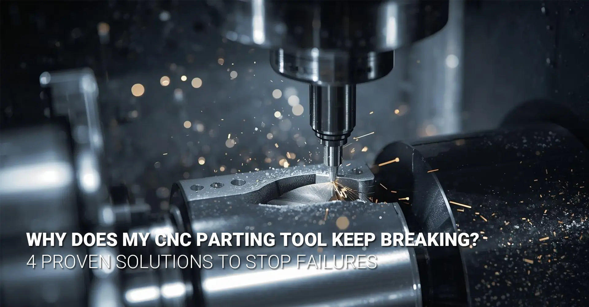
Why Does My CNC Parting Tool Keep Breaking? 4 Proven Solutions to Stop Failures

If you've ever watched a parting tool snap in the middle of a production run, you know the sinking feeling that follows. Not only do you lose the part, but you also face downtime, tool replacement costs, and the pressure to figure out what went wrong. CNC turning parting off issues plague machine shops everywhere, from small job shops to large manufacturing facilities. However, the good news is that most parting tool failures are preventable once you understand the root causes and apply proven solutions.
Quick Answer: Why Do Parting Tools Break?
Most parting tool breakage happens because of three interconnected problems:
- Poor rigidity in your tool setup, allowing deflection and vibration
- Chip evacuation failure where chips pack into the groove and recut themselves
- Wrong cutting parameters especially feeds that are too slow, causing rubbing instead of cutting
Additionally, using incorrect tool geometry for your specific material accelerates wear and increases the chance of sudden failure. The solution isn't buying more expensive tools—it's understanding how rigidity, chip formation, and cutting parameters work together. This guide provides four proven strategies that can extend your cutoff tool life CNC operations by up to 300%.
Whether you're troubleshooting persistent breakage problems or looking to improve your shop's parting operations, this comprehensive guide breaks down exactly what causes tools to fail and, more importantly, how to prevent it. Moreover, we'll explore real-world solutions that machinists have used successfully, including insights from community discussions on CNC turning part off tool breakage Reddit forums. Let's dive into the four critical areas that will transform your parting operations from unpredictable to reliable.
Table of Contents
- What Causes Tool Rigidity Problems and How Do You Fix Them?
- How Can You Master Chip Control and Coolant Strategy?
- Which Cutting Parameters Prevent Breakage Instead of Causing It?
- When Should You Change Your Tool Geometry or Upgrade Your Sstem?
What Causes Tool Rigidity Problems and How Do You Fix Them?
Rigidity forms the foundation of successful parting operations. Without it, even perfect cutting parameters and premium tools will fail. When your setup lacks rigidity, the tool deflects away from the workpiece during the cut, creating vibration, chatter, and ultimately catastrophic breakage. Therefore, understanding and maximizing rigidity should be your first priority when addressing CNC parting tool breakage.
The Core Rigidity Problem
The number one cause of parting tool failures is insufficient rigidity in the cutting system. This problem manifests in several ways:
- Excessive tool overhang from the turret or tool holder
- Weak or worn tool holders that allow movement
- Inadequate workpiece support causing the part to deflect
- Spindle bearing wear creating runout and vibration
When any of these factors are present, the tool cannot maintain consistent contact with the material. Consequently, cutting forces push the tool away, creating a bouncing action that generates heat, accelerates wear, and leads to sudden failure.
Building a Rigid Parting Setup
Minimize Tool Overhang
The relationship between overhang and rigidity follows the cubic law—doubling the overhang reduces rigidity by eight times. For this reason, always use the shortest possible tool extension that still provides adequate clearance. In practical terms, your blade should extend no more than necessary to clear the part diameter plus 0.25 inches for safety.
Select the Correct Blade Width
Blade width directly impacts rigidity. A wider blade resists deflection better but requires more power to push through the material. Use this guideline:
- Parts under 1 inch diameter: 0.093" to 0.125" blade width
- Parts 1 to 2 inches diameter: 0.125" to 0.187" blade width
- Parts over 2 inches diameter: 0.187" to 0.250" blade width or consider a specialized system
Verify Tool Holder Condition
Even with the right blade, a worn or damaged tool holder undermines rigidity. Check for:
- Cracks in the holder body
- Worn clamping surfaces
- Loose mounting screws
- Proper seating of the blade in the holder pocket
Furthermore, ensure your tool holder mounting surface on the turret is clean and free from chips or burrs. A contaminated mounting surface can tilt the entire holder, creating runout and instability.
Support Long Parts Properly
When parting off long workpieces, the part itself can flex and vibrate. Use a tailstock or steady rest to support the work, especially when the unsupported length exceeds three times the diameter. This support becomes critical when working with CNC machining service projects that involve slender components.
Check Spindle Condition
A worn spindle with excessive bearing play creates runout that translates directly to parting tool vibration. If you notice inconsistent parting performance despite good tool setup, measure your spindle runout with a dial indicator. Total indicated runout should be less than 0.0005" at the part location for precision parting operations.
How Can You Master Chip Control and Coolant Strategy?
After establishing rigidity, chip evacuation becomes your next critical focus. The narrow groove created during parting off presents a unique challenge—chips have limited space to escape and can easily pack into the cut. When this happens, the tool recutting those chips experiences dramatically increased forces, leading to rapid tool wear or sudden breakage. Therefore, reducing vibration in CNC parting off requires excellent chip control combined with strategic coolant application.
The Chip Evacuation Challenge
Chips are simultaneously your biggest problem and your best diagnostic tool during parting operations. Ideal chips should be:
- Broken into short segments (not long strings)
- Evacuated quickly from the cutting zone
- Uniform in thickness indicating consistent cutting action
- Free of discoloration showing adequate cooling
When chips fail to evacuate properly, they pack into the groove, get recut by the tool, work-harden, and create a cascade of problems that ends in tool failure.

Chip Control and Coolant Mastery
Select Insert Geometry for Your Material
Chipbreaker design on your parting insert plays a crucial role in chip formation. Different materials require different approaches:
For Aluminum and Brass: Use inserts with positive rake angles and open chipbreaker designs. These materials are free-machining and produce chips easily, so you need geometry that allows chips to flow freely without restriction.
For Steel and Stainless: Choose inserts with engineered chipbreaker grooves that curl and break chips into manageable segments. The chipbreaker must be aggressive enough to control the chip but not so restrictive that it increases cutting forces excessively.
For Tough Materials: When working with materials like Inconel or hardened steels in industrial machinery applications, you need extremely robust chipbreaker designs that can withstand high forces while still breaking chips effectively.
Apply Coolant Strategically
Coolant serves three critical functions in parting operations: chip flushing, heat removal, and lubrication. However, generic coolant application often fails to address all three effectively. Instead, follow these best practices for CNC parting off operations:
High-Pressure, Directed Flow: Position your coolant nozzle to aim directly into the parting groove from the side. Pressure should be at least 300 PSI (higher for difficult materials) to blast chips out of the cut as they form. Low-pressure flood coolant simply cannot overcome the chip-packing tendency in narrow grooves.
Maintain Proper Concentration: Mix ratio matters significantly. Too weak, and you lose lubrication; too strong, and you create foaming that prevents coolant from reaching the cutting edge. Test your coolant concentration weekly and maintain it within the manufacturer's specified range (typically 5-10% for synthetic coolants).
Consider Through-Tool Coolant: For production parting operations or difficult materials, through-tool coolant delivery provides superior results. The coolant emerges directly at the cutting edge, ensuring maximum effectiveness. Many modern parting blade holders include internal coolant passages specifically for this purpose.
Match Feed Rate to Chip Formation
Your feed rate directly determines chip thickness, which affects how easily chips evacuate from the cut. Counterintuitively, many operators run feeds too slowly when they encounter problems, making the situation worse. A very slow feed creates thin chips that tend to pack and recut rather than evacuate cleanly.
Instead, use these feed rate targets as starting points:
- Aluminum: 0.004" to 0.008" per revolution
- Mild Steel: 0.003" to 0.006" per revolution
- Stainless Steel: 0.002" to 0.004" per revolution
Which Cutting Parameters Prevent Breakage Instead of Causing It?
Once you've addressed rigidity and chip control, cutting parameters become your fine-tuning mechanism for turning tool breakage prevention. Many machinists operate under outdated assumptions about feeds and speeds that actually increase the likelihood of failure. In fact, the most common parameter mistake—running too slowly—causes more tool breakage than any other programming error. Let's explore how to select parameters that protect your tools while maximizing productivity.
The Parameter Paradox
The instinct to slow down when facing tool breakage is almost always wrong. This counterintuitive reality catches many machinists off guard. Here's why slow parameters cause problems:
- Rubbing instead of cutting generates excessive heat without removing material efficiently
- Work hardening the surface creates an increasingly difficult cutting condition
- Thin chip formation leads to chip packing rather than evacuation
- Tool edge degradation from heat rather than normal wear
In contrast, appropriate feeds and speeds create clean cutting action where the tool shears material efficiently, produces chips that evacuate properly, and generates manageable heat that coolant can remove effectively.
Parameter Selection Strategy
Understanding the Feed Rate Principle
Feed rate determines chip thickness, which fundamentally affects every aspect of the parting operation. When you implement how to prevent tool breakage when parting off CNC machines, feed rate optimization should be your primary focus.
Chip Thickness and Cutting Action: A chip must be thick enough to allow the tool to cut rather than rub. This thickness depends on the tool's cutting edge radius. Generally, minimum chip thickness should be at least 30% of the edge radius. For a typical parting insert with a 0.001" edge radius, your minimum chip thickness should be 0.0003" or greater.
Calculating Optimal Feed: Your feed per revolution creates the uncut chip thickness. For most parting operations, target chip thickness between 0.002" and 0.006". This range provides enough material for efficient cutting while remaining within the capability of the tool edge.
The Constant Feed Rule: Never pause or slow the feed during the parting cut. Even a momentary hesitation allows the tool to rub and work-harden the material, creating a hard spot that dramatically accelerates tool wear. Program your feeds to maintain constant motion from start to finish.
Speed Selection by Material
Cutting speed (surface feet per minute) affects tool temperature and wear rate. Different materials require vastly different approaches:
Aluminum (6061, 7075): Run speeds between 500 and 800 SFM. Aluminum conducts heat well and machines easily, allowing aggressive speeds. Pair with sharp, positive-rake inserts and high coolant flow. These conditions are common in CNC turning operations for aerospace components.
Mild Steel (1018, 1045): Use speeds between 300 and 400 SFM. Steel generates more heat than aluminum but machines predictably. Focus on maintaining consistent feeds to prevent work hardening. The material's response to heat treatment affects machinability significantly in CNC metals plastics applications.
Stainless Steel (304, 316): Reduce speeds to 200-300 SFM. Stainless work-hardens readily and generates substantial heat. Use rigid setups, aggressive chip breaking geometry, and copious coolant. Never let the tool dwell in the cut.
Brass and Bronze: Run at 400-600 SFM. These materials machine beautifully but can be abrasive. Sharp tools with positive geometry work best, and many operations can run successfully without coolant.
Depth of Cut Considerations
In parting operations, depth of cut equals the feed per revolution since you're feeding radially into the part. However, the relationship between your programmed feed and actual material removal rate changes as you approach the center of the part.
Decreasing Cutting Speed: As the tool approaches the part center, the diameter decreases, which means the cutting speed (SFM) also decreases even though your spindle RPM remains constant. This changing condition means that parameters optimal at the part OD may not be ideal at the center.
Constant Surface Speed Programming: If your machine supports it, use constant surface speed (CSS) mode for parting operations. CSS maintains optimal cutting speed by automatically increasing spindle RPM as the effective diameter decreases. This feature significantly improves tool life and finish quality.
Parameter Adjustment Strategy
When troubleshooting parting problems, adjust parameters systematically:
- Start with standard feeds for your material (as listed above)
- If you experience chatter, slightly increase feed rate first before decreasing it
- If tool life is poor, verify coolant effectiveness before changing speeds
- If surface finish suffers, check tool sharpness and reduce feed slightly
- Document successful parameters for future reference on similar parts
Remember that successful parameters depend on the interaction of all factors—your machine rigidity, tool geometry, material condition, and setup quality all influence what works best.
When Should You Change Your Tool Geometry or Upgrade Your System?
Sometimes persistent parting problems stem not from poor technique but from using inadequate tooling for your application. Knowing when to change insert geometry or upgrade to a specialized parting system can save thousands of dollars in scrapped parts and wasted time. Furthermore, as your work evolves toward larger parts, tougher materials, or tighter tolerances, your tooling needs change accordingly. This section helps you identify when you've outgrown your current setup and what solutions will solve your specific challenges.
Recognizing When to Change Insert Geometry
Your insert geometry should match both your material and your desired surface finish requirements. Signs that you need different geometry include:
- Built-up edge on the tool indicating wrong rake angle for the material
- Excessive burr formation suggesting geometry too aggressive or dull
- Rapid flank wear showing inadequate edge preparation for material hardness
- Inconsistent chip formation revealing chipbreaker design mismatch
Tool Selection and System Upgrades
Insert Geometry Selection
Modern parting inserts offer numerous geometry variations optimized for specific conditions:
Rake Angle Options:
-
Positive Rake (5-7 degrees): Best for aluminum, brass, and other free-machining materials. Creates a sharp cutting edge that shears material easily with minimal force. Use when your machine has limited power or when finishing requirements are critical.
-
Neutral Rake (0 degrees): Provides versatility for general steel machining. Balances edge strength with cutting efficiency. This geometry handles interrupted cuts better than positive rake while still cutting efficiently.
-
Negative Rake (-5 to -7 degrees): Reserved for the toughest materials like hardened steel or Inconel. Provides maximum edge strength but requires more power. The robust edge resists chipping in difficult applications.
Edge Preparation:
Sharp inserts cut aluminum and brass beautifully but chip quickly in harder materials. Honed or chamfered edges provide the durability needed for steel and stainless steel while sacrificing some sharpness. Match edge preparation to material hardness—sharper for softer materials, more robust preparation for harder ones.
Coating Selection:
Uncoated carbide works well for aluminum (coatings can lead to built-up edge). TiN coating provides good general-purpose performance in steel. TiAlN coating excels in stainless steel and heat-resistant alloys. Diamond coating delivers exceptional performance in abrasive materials like aluminum-silicon alloys or carbon fiber composites.
When Standard Tooling Isn't Enough
Several indicators suggest you need to upgrade beyond standard parting tools:
Large Diameter Parts: When parting diameters exceed 2 inches, standard tool holders often lack the rigidity needed. Specialized large-diameter parting systems feature guided blades that resist deflection and often include high-pressure coolant delivery systems built into the holder.
Tough Material Requirements: If you regularly machine stainless steel, Inconel, or titanium, investing in a specialized parting system pays dividends. These systems typically offer:
- Enhanced rigidity through guided blade designs
- Integral high-pressure coolant delivery
- Larger blade sections that resist deflection
- Optimized geometries for difficult materials
Tight Tolerance Demands: When parted-off length must be held to ±0.005" or tighter, standard tools often cannot deliver consistent results. Specialized systems with guided blades minimize deflection, ensuring repeatable part-off lengths. Additionally, these systems often accommodate wider blades that maintain better straightness under load.
High-Volume Production: In production environments where tool life consistency directly impacts profitability, advanced parting systems provide:
- Predictable tool wear patterns
- Extended tool life through better heat management
- Reduced cycle time through higher feed rates
- Lower cost per part despite higher initial investment
Evaluating System Upgrade Options
When considering an upgrade, calculate your return on investment:
Current Costs: Document your existing tool cost per part, including:
- Insert cost divided by parts per edge
- Time lost to tool changes
- Scrap from tool failures
- Labor for troubleshooting problems
Projected Savings: Better tooling typically reduces:
- Tool cost by 30-50% through longer life
- Scrap by 60-80% through more reliable performance
- Cycle time by 20-40% through higher feeds and speeds
- Setup time through better repeatability
For most shops, the investment in premium parting tooling pays for itself within 3-6 months of regular use.
Blade Holder Systems:
Standard ER Collet Holders: Economical and adequate for small parts in free-machining materials. Limited rigidity restricts performance in demanding applications.
Rigid Block Holders: Provide excellent rigidity through mechanical clamping of the blade on multiple surfaces. Good choice for general shop work up to 2-inch diameters.
Guided Blade Systems: Feature guide pads or rails that support the blade during the cut. Dramatically improve performance on large diameters or tough materials.
High-Pressure Coolant Holders: Integrate coolant delivery passages within the holder body, directing coolant precisely at the cutting edge. Essential for stainless steel and heat-resistant alloys.
Making the Upgrade Decision
Consider upgrading when you answer "yes" to any of these questions:
- Do you regularly part materials like 304 stainless, Inconel, or titanium?
- Are parting diameters frequently over 2 inches?
- Does poor tool life in parting operations significantly impact your shop's profitability?
- Do you struggle to hold length tolerances on parted-off components?
- Have you optimized parameters and setup but still experience consistent problems?
If you answered yes to multiple questions, an upgraded parting system will likely provide substantial returns. Start by consulting with tooling specialists who can recommend systems matched to your specific applications and machine capabilities.
Conclusion
CNC parting tool breakage doesn't have to be an inevitable frustration in your shop. By systematically addressing the four critical areas—rigidity, chip control, cutting parameters, and tool selection—you can transform parting from an unpredictable operation into a reliable, productive process.
Remember that these factors work together as a system. Excellent rigidity means nothing if chips pack into the cut. Perfect parameters fail when using the wrong insert geometry. Success comes from understanding how each element influences the others and optimizing your entire approach.
Start with the basics: maximize rigidity by minimizing overhang and using appropriate blade widths. Then ensure proper chip evacuation through correct insert geometry and strategic coolant application. Next, optimize your cutting parameters—and remember that faster feeds often solve more problems than slower ones. Finally, recognize when your application demands specialized tooling that standard systems cannot provide.
The knowledge shared here comes from decades of combined machining experience, real-world troubleshooting in production environments, and insights from community discussions where machinists share what actually works. Apply these principles systematically, document what works in your specific situation, and you'll see dramatic improvements in tool life, part quality, and productivity.
Parting operations will never be completely trouble-free—the nature of the process ensures some challenges will always exist. However, with the right approach, you can extend tool life by 300% or more, eliminate most catastrophic failures, and gain the confidence that comes from understanding why your tools work the way they do.
External Resources
[CNC turning parting off issues][^1]
[cutoff tool life CNC][^2]
[turning tool breakage prevention][^3]
[reducing vibration in CNC parting off][^4]
---
[^1]: Understanding these issues can help improve your machining process and reduce downtime.
[^2]: Exploring this resource will provide insights into techniques that can significantly extend the lifespan of your CNC tools.
[^3]: This link will offer valuable strategies and tips to minimize tool breakage, enhancing productivity and reducing costs.
[^4]: Explore this link to discover techniques that can enhance precision and extend tool life during CNC parting off.


