What Are the Best 5-Axis CAM Software Strategies to Cut Programming Time in Half?
What Are the Best 5-Axis CAM Software Strategies to Cut Programming Time in Half?

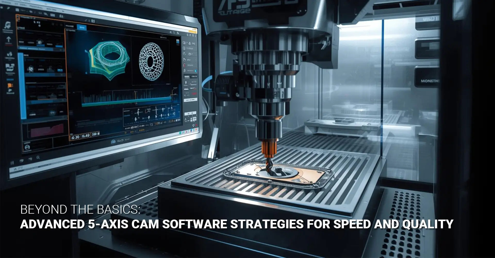
Are you spending hours programming 5-axis toolpaths only to find your cycle times longer than expected? Many machinists face this challenge daily. The good news is that the machining community on Reddit has been sharing proven 5 axis CAM software strategies that dramatically reduce programming time while improving part quality. Whether you're working on complex automotive components or industrial machinery parts, mastering these techniques will transform your workflow. In this guide, you'll discover actionable methods for roughing, finishing, and collision avoidance that professional programmers use every day.
Quick Reference: Essential 5-Axis CAM Strategies
| Strategy | Primary Benefit | Best Used For |
|---|---|---|
| Tool Axis Control | Prevents collisions and maintains cutting contact | All 5-axis operations |
| Lead/Tilt Angles | Reduces tool deflection and improves finish | Sidewall machining |
| Rest Machining | Eliminates air cuts and saves time | Roughing operations |
| Axis Smoothing | Removes witness marks | Finishing passes |
| Boundary Isolation | Applies tailored strategies per region | Complex geometries |
Key Takeaway: The difference between frustrating 5-axis programming and smooth operation comes down to controlling your tool axis properly. Moreover, understanding when to apply specific strategies makes all the difference in your results.
Now that you've seen the overview, let's dive into each strategy in detail. First, we'll explore how 5-axis thinking differs from traditional 3-axis programming. Then, we'll break down the specific settings that boost your material removal rates. After that, you'll learn finishing techniques that eliminate surface defects. Finally, we'll cover the critical decision between tilt angles and axis limits.
Table of Contents
- How Does Tool Axis Control Differ Between 3-Axis and 5-Axis Machining?
- Which CAM Settings Boost Material Removal Rate in 5-Axis Roughing?
- What Techniques Prevent Gouging in Complex 5-Axis Finishing Passes?
- When Should You Use Tilt Angles vs. Tool Axis Limits in Your Toolpath?
How Does Tool Axis Control Differ Between 3-Axis and 5-Axis Machining?
Understanding the Fundamental Shift
When you move from 3-axis to 5-axis machining, everything changes about how you approach programming. In 3-axis work, your tool always points straight down, which means you only worry about X, Y, and Z positions. However, 5-axis machining introduces rotational axes that control where your tool points at any given moment. This fundamental difference requires you to think differently about every toolpath you create.
Core Differences at a Glance
Tool axis control strategies represent the biggest paradigm shift in 5-axis programming. Here's what separates the two approaches:
- 3-Axis Approach: Tool remains perpendicular to the work surface
- 5-Axis Approach: Tool orientation changes dynamically throughout the cut
- 3-Axis Limitation: Can only access features from the top
- 5-Axis Advantage: Reaches undercuts, complex curves, and deep pockets
- 3-Axis Programming: Focuses solely on tool tip position
- 5-Axis Programming: Manages both tool tip location and tool axis direction

Diving Deeper into Tool Axis Management
The real power of 5-axis machining comes from strategic tool orientation control. Instead of thinking "where does my tool need to be," you must ask "where does my tool need to be AND how should it be pointing?" This dual consideration affects everything from your CNC machining service selection to your final part quality.
Lead angles tilt the tool forward or backward in the direction of travel. Therefore, using a small lead angle (typically 5-15 degrees) helps you maintain better chip evacuation and reduces cutting forces. Lag angles, on the other hand, tilt the tool backward, which is useful for specific applications like turbine blade machining.
Additionally, you need to set axis limits that define the safe working envelope for your tool. These limits prevent the tool from rotating into positions that would cause collisions with the part, fixture, or machine itself. Most CAM software allows you to define a cone angle that restricts how far the tool can tilt from vertical.
Understanding these concepts becomes crucial when programming custom CNC milling services for clients with complex part geometries.
Which CAM Settings Boost Material Removal Rate in 5-Axis Roughing?
The Challenge of Consistent Engagement
Roughing operations remove the bulk of material quickly, but inefficient toolpaths waste both time and tool life. The key challenge is maintaining consistent tool engagement with the workpiece. When your tool enters and exits the material repeatedly, or cuts through air, you're losing money with every cycle.
Top Settings for Faster Roughing
Mastercam 5 axis toolpath optimization starts with these critical settings:
- Rest Machining: Programs your toolpath to cut only remaining material after previous operations
- Morph Between Boundaries: Creates smooth transitions between cutting regions
- Constant Scallop Height: Maintains uniform stepover across curved surfaces
- Adaptive Tool Axis: Presents more flute length to the material for deeper cuts
Each of these settings addresses a specific inefficiency in traditional roughing approaches. As a result, you can achieve 30-50% faster cycle times compared to basic toolpath strategies.
Step-by-Step Roughing Strategy
First, analyze your part geometry to identify areas with significant material removal. Then, set up your roughing operation using these proven techniques:
Choose the Right Strategy: Start with a helical entry to reduce shock loading on your tool. Subsequently, use a trochoidal or dynamic milling pattern for heavy material removal. This approach works exceptionally well for CNC turning operations that require multiple roughing passes.
Set Your Axial Depth: Calculate the maximum axial depth of cut based on your tool's flute length and the material hardness. Generally, you want to use 50-75% of the available flute length during roughing. However, harder materials require more conservative settings.
Adjust Radial Engagement: Instead of taking a full-width cut, reduce your radial engagement to 40-50% of tool diameter. This technique allows you to increase your feed rate significantly while maintaining tool life.
Control Tool Axis Position: Orient your tool axis relative to the surface normal to present fresh cutting edges to the material. For example, tilting the tool 10-15 degrees can allow you to take deeper axial cuts while reducing side loading.
Enable Stock Recognition: Modern CAM software can simulate previous operations and automatically avoid cutting areas that have already been machined. Therefore, activating this feature eliminates wasteful air cutting.
Implement Boundary-Based Programming: Create boundaries around specific regions that need different strategies. Consequently, you can use aggressive settings in open areas while applying conservative parameters near critical features.
These 5-axis machining efficiency tips work together to create roughing operations that are both fast and safe. Furthermore, they reduce wear on your cutting tools, which lowers your overall production costs.
What Techniques Prevent Gouging in Complex 5-Axis Finishing Passes?
Common Finishing Problems
Finishing passes determine your final part quality, yet many programmers struggle with surface defects. Witness marks appear as visible lines where the tool axis suddenly changed direction. Meanwhile, gouges occur when the tool holder or spindle collides with part features. Additionally, inconsistent surface finish happens when the tool axis moves erratically between cutting points.
Essential Collision Avoidance Checklist
Avoiding gouges in 5-axis machining requires attention to multiple factors:
- ✓ Import complete tool assembly models (tool, holder, spindle)
- ✓ Enable holder collision checking in your CAM software
- ✓ Define keep-out zones around fixtures and clamps
- ✓ Set appropriate axis limits to prevent extreme orientations
- ✓ Use tool axis smoothing functions
- ✓ Verify toolpaths with solid simulation before cutting

Advanced Finishing Techniques
Achieving mirror-quality surfaces requires mastering several advanced techniques. First, let's address tool axis smoothing, which is perhaps the most important finishing parameter.
Tool Axis Smoothing: This function prevents sudden jerky movements by creating smooth transitions between tool orientations. Most CAM software for complex parts includes smoothing algorithms that you can adjust. Start with moderate smoothing (around 50%) and increase if you still see witness marks.
Cusp Height Management: Instead of trying to achieve a perfectly perpendicular tool orientation at every point, accept a small consistent cusp height. For ball-nose end mills, a cusp height of 0.001-0.003 inches typically produces excellent results. Smaller cusp heights mean more passes, so find the balance between surface quality and cycle time.
Simultaneous 5-axis programming becomes essential when finishing complex sculptured surfaces. Unlike 3+2 positioning strategies, true simultaneous motion allows the tool to maintain optimal contact throughout the cut. This approach is particularly valuable for automotive applications where surface quality directly affects aerodynamics and aesthetics.
Collision Detection Refinement: Don't just check for tool tip collisions. Instead, verify that your entire tool assembly clears the part. Load accurate models of your tool holders and spindle into your CAM system. Then, run collision checking with these components visible. You'll often discover potential crashes that wouldn't be obvious from looking at the tool tip path alone.
Strategic Stepover Selection: Your stepover distance affects both finish quality and cycle time. Smaller stepovers create smoother surfaces but take longer. However, the relationship isn't linear. Reducing your stepover from 0.020" to 0.010" doesn't double your cycle time because the tool spends less time changing direction.
Feed Rate Adjustment: Maintain consistent feed rates throughout your finishing pass. Sudden speed changes can leave marks on your part surface. Therefore, use your CAM software's feed rate smoothing features to create gentle acceleration and deceleration curves.
When Should You Use Tilt Angles vs. Tool Axis Limits in Your Toolpath?
Clearing Up the Confusion
Many programmers struggle to understand when to use tilt angles versus tool axis limits. Both control tool orientation, yet they serve different purposes. Understanding this distinction is crucial for creating reliable, efficient toolpaths.
Quick Decision Matrix
| Scenario | Use Tilt Angle | Use Axis Limits |
|---|---|---|
| Vertical wall finishing | Yes (10-15°) | Yes (cone limit) |
| Open surface roughing | Optional | Yes (avoid extremes) |
| Deep pocket machining | Yes (toward center) | Yes (prevent holder collision) |
| Sculptured surface finishing | No (let CAM decide) | Yes (safety envelope) |
Real-World Application Guide
Lead and tilt angle optimization requires understanding your specific machining scenario. Let's break down each approach:
Fixed Tilt Angle Applications: When you're machining vertical or near-vertical walls, applying a fixed tilt angle of 10-15 degrees provides significant benefits. The tool leans away from the wall, which uses the side of the flute for cutting rather than the tip. Consequently, you get better surface finish and reduced tool deflection.
For example, when programming industrial machinery components with deep pockets, tilting your tool toward the pocket center prevents the holder from hitting the walls. This simple adjustment can mean the difference between a successful program and a crashed machine.
Tool Axis Limits (Cone Limits): Think of axis limits as your safety boundaries. They define an imaginary cone within which your tool axis must remain. Setting a 45-degree cone limit, for instance, means your tool can tilt up to 45 degrees from vertical in any direction.
These limits become critical when programming around fixtures, clamps, or complex part features. Instead of manually adjusting every toolpath section, you set the limit once, and your CAM software automatically keeps the tool within safe parameters.
Combining Both Strategies: The most sophisticated programs use both tilt angles and axis limits together. For instance, you might set a 15-degree tilt toward a wall while also defining a cone limit that prevents the tool from rotating too far horizontally. This combination gives you precise control where you need it while maintaining overall safety.
Boundary-Based Strategy Selection: Here's a technique that experienced programmers swear by: create boundaries around different regions of your part. Then, apply different tilt angle and limit combinations to each region. Open areas can use aggressive settings for speed. Meanwhile, areas near critical features use conservative parameters for safety.
This targeted approach often cuts programming time significantly. Instead of creating multiple separate operations, you create one operation with region-specific controls. Moreover, this method reduces the risk of errors because you're managing fewer toolpaths overall.
Practical Testing Protocol: Before running any new 5-axis program, follow this verification sequence. First, simulate the toolpath with your complete tool assembly visible. Next, check for any axis limit violations or collision warnings. Then, verify that the tool maintains proper cutting contact throughout the operation. Finally, run the program at reduced feed rate for the first part.
Conclusion
Mastering 5-axis CAM programming doesn't happen overnight, but these strategies will dramatically improve your results. We've covered how tool axis control differs from 3-axis thinking, which settings boost your material removal rate, techniques for preventing gouges, and when to use tilt angles versus axis limits. Each strategy addresses specific challenges that slow down production and compromise quality.
The Reddit machining community continues to prove that shared knowledge accelerates everyone's progress. Start by implementing one strategy on your next project. Pick the technique that addresses your biggest current pain point. Then, gradually incorporate the other methods as you gain confidence.
Remember, efficient 5-axis programming combines smart strategy selection with patient practice. Your first attempts might not be perfect, but each project teaches you something valuable about managing tool axis motion and avoiding collisions.
Ready to take your programming skills further? Try testing boundary-based strategies on a complex part this week. You'll likely find that the time you invest in setup pays off many times over in reduced cycle time and improved part quality.
Recommended Resources
[5 axis CAM software strategies][^1]
[Mastercam 5 axis toolpath optimization][^2]
[5-axis machining efficiency tips][^3]
[Lead and tilt angle optimization][^4]
[Simultaneous 5-axis programming][^5]
[Avoiding gouges in 5-axis machining][^6]
---
[^1]: Explore this link to discover effective strategies that can enhance your 5 axis machining processes.
[^2]: This resource will provide insights into optimizing toolpaths, improving efficiency and precision in your machining projects.
[^3]: Explore this link to discover expert strategies that can significantly enhance your 5-axis machining processes.
[^4]: This resource will provide insights into how optimizing lead and tilt angles can boost your machining accuracy and efficiency.
[^5]: Understanding this concept can enhance your machining efficiency and precision.
[^6]: Learning effective techniques can significantly improve your machining quality and reduce waste.
Community Forums:
- Reddit r/Machinists - Active discussions on 5-axis techniques
- CNCzone Multi-Axis Machining Forum - Detailed technical threads
- Practical Machinist 5-Axis Programming Section
Manufacturer Resources:
- Haas 5-Axis Programming Best Practices Guide
- DMG MORI Multi-Axis Machining Handbook
- Makino Advanced Programming Strategies


