How Do You Pick the Right CNC Insert Coating to Cut Machining Costs?
How Do You Pick the Right CNC Insert Coating to Cut Machining Costs?

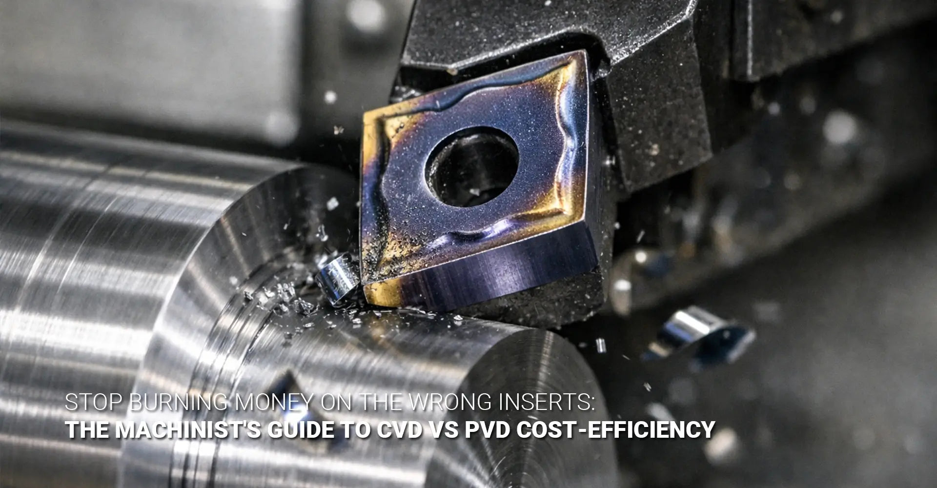
Choosing between CVD and PVD coatings can make or break your machining budget. Most shops waste thousands of dollars each year by selecting inserts based on supplier recommendations rather than understanding how coating physics affects their specific operations. The wrong coating choice leads to premature tool failure, unexpected downtime, and inflated cost per part. Whether you're running CNC turning operations or complex custom CNC milling services, understanding CNC insert coating selection is critical to profitability.
Quick Answer Box
CVD coatings work best for continuous, high-speed cuts in steel and cast iron due to their thickness (8-15μm) and heat resistance. Meanwhile, PVD coatings excel in interrupted cuts, finishing operations, and stainless steel because they stay sharp and handle mechanical shock better. Your material, cutting speed, and operation stability determine which coating saves you money.
However, understanding this basic distinction is just the starting point. To truly reduce your machining cost per part, you need to know why these coatings behave differently, how to diagnose coating failures, and what specific conditions trigger the need to switch. Let's break down everything you need to make smarter insert purchases for your CNC machining service operations.
Table of Contents
- What Makes CVD and PVD Coatings Behave So Differently?
- Where Does CVD Coating Excel (and Where Does It Fail Completely)?
- Where Does PVD Coating Excel (and Where Does It Fall Short)?
- How Can You Tell If You're Using the Wrong Coating Type?
- Your Decision Matrix: Coating vs. Material & Operation
- The Coolant Debate: Does Flood Cooling Help or Hurt Your CVD Coating?
- Actionable Summary: A 5-Step Checklist for Your Next Insert Order
What Makes CVD and PVD Coatings Behave So Differently?
The fundamental difference between CVD (Chemical Vapor Deposition) and PVD (Physical Vapor Deposition) lies in how they're applied and what that process creates. These aren't just different brand names—they represent entirely different material structures that respond to heat, shock, and wear in opposite ways. Understanding CVD vs PVD coating characteristics is the foundation of smart insert selection.
The Thickness Gap
CVD coatings are applied at 1000°C, creating a thick (8-15μm), chemically bonded layer that's incredibly heat-resistant but slightly brittle. In contrast, PVD coatings are deposited at 500°C, resulting in a thin (2-4μm), sharp edge that maintains toughness but offers less thermal protection. This difference in carbide insert coating thickness directly impacts performance.
Why Thickness Matters
This thickness difference of 10+ micrometers translates directly to performance in CNC metals and plastics machining. CVD's thick alumina (Al2O3) layer acts like a thermal barrier, protecting the carbide substrate from temperatures exceeding 800°C during high-speed steel cutting. The coating absorbs heat cycles that would otherwise soften the cutting edge.
On the other hand, PVD's thin coating preserves the sharp edge geometry created during insert grinding, which is critical for finishing operations where surface quality matters. The high-temperature CVD process creates a slight edge rounding (honing effect) that dulls the cutting edge by 15-25μm, making it unsuitable for precision finishing.
Additionally, PVD coatings like TiAlN remain ductile enough to resist micro-chipping when the tool encounters interruptions, such as milling or turning keyways. This mechanical resilience comes from the lower deposition temperature, which doesn't alter the carbide substrate's toughness properties. These characteristics become especially important in automotive manufacturing where precision and consistency are paramount.
Where Does CVD Coating Excel (and Where Does It Fail Completely)?
CVD-coated inserts dominate in specific machining scenarios where heat and abrasion are the primary enemies. Recognizing these conditions helps you avoid paying for coating properties you don't actually need, particularly in industrial machinery applications.
The CVD Sweet Spot
CVD coatings perform best in continuous turning of steel alloys (1018, 4140) at speeds above 400 SFM and cast iron machining where abrasive wear dominates. However, they fail catastrophically in interrupted cuts and fine finishing work. This is why CVD for high speed operations has become the industry standard.
When CVD Delivers Maximum Value
The sweet spot for CVD coatings is continuous roughing and semi-finishing of medium to high carbon steels. When cutting 4140 alloy steel at 500-700 SFM with depth of cut at 0.100-0.150 inches, the thick Al2O3 layer prevents crater wear behind the cutting edge—a common failure mode at these temperatures. This makes CVD the preferred insert coating for steel in most production environments.
Similarly, gray cast iron machining benefits enormously from CVD because the abrasive graphite particles would rapidly wear through thin PVD coatings. Data shows CVD inserts lasting 3-4 times longer in cast iron compared to PVD equivalents, making them the go-to insert coating for cast iron applications.
Where CVD Falls Short
Nevertheless, CVD's brittleness becomes a liability in milling operations or turning interrupted surfaces like splined shafts. The thermal cycling from entry/exit shocks creates micro-cracks in the thick coating layer, propagating into catastrophic failure. Thermal cracking inserts are a telltale sign you're using CVD in the wrong application.
Furthermore, the edge honing inherent to CVD processing produces poor surface finishes below 63 Ra, making these inserts unsuitable for finish passes where tolerances under 0.002 inches matter. In these cases, switching to PVD delivers better results and lower costs.
Where Does PVD Coating Excel (and Where Does It Fall Short)?
PVD-coated inserts shine in completely different conditions than CVD. Understanding where PVD provides superior cost per part prevents you from defaulting to "general purpose" CVD when a cheaper, longer-lasting PVD insert would perform better.
PVD's Natural Habitat
PVD coatings deliver exceptional performance in interrupted cuts (milling, boring interrupted holes), stainless steel machining, and finishing operations requiring sharp edges. They struggle in continuous, high-heat applications where the thin coating gets overwhelmed. This is why PVD for interrupted cut operations has become the recommended best practice.
The Sharp Edge Advantage
The thin, tough nature of PVD coatings makes them ideal for mechanical shock absorption. When face milling 316 stainless steel—a notoriously "sticky" material—the sharp PVD edge slices cleanly without building up material on the cutting edge (BUE - Built-Up Edge). This same sharpness produces mirror-like finishes in aluminum and low-carbon steels, often achieving 32 Ra or better without secondary operations.
PVD's lower deposition temperature preserves the substrate's fracture toughness, which is why these inserts resist chipping when entering/exiting cuts in milling or turning profiles with grooves. This property is especially valuable when machining complex geometries common in precision industries.
PVD's Limitations
However, PVD coatings fail quickly in continuous operations above 600 SFM in steel because the thin 2-4μm layer cannot dissipate heat effectively. The coating wears through in minutes, exposing the unprotected carbide substrate to rapid flank wear. Likewise, in abrasive cast iron, PVD coatings offer minimal protection against the constant grinding action of graphite and silica particles, resulting in tool life that's 25-40% of what CVD provides.
How Can You Tell If You're Using the Wrong Coating Type?
Your failed inserts tell a detailed story about what went wrong. Learning to read wear patterns turns every tool failure into a diagnostic opportunity that saves money on your next order. Proper insert wear analysis is a skill every machinist should develop.
Reading the Signs
Thermal cracking and crater wear indicate you need CVD's heat resistance. Edge chipping, micro-fractures, and rapid coating delamination signal you need PVD's toughness and sharp geometry.
The Diagnostic Process
When examining failed inserts under magnification, specific patterns reveal exactly what went wrong. Thermal cracking appears as a spider-web network of fine lines across the rake face, particularly near the cutting edge. This happens when heat exceeds the coating's capacity, causing differential expansion between the coating layers and substrate. If you see this pattern, switching to a thicker CVD coating (or increasing the Al2O3 layer thickness) addresses the root cause.
Crater wear—a depression forming behind the cutting edge—occurs when hot chips remain in contact with the tool too long, chemically dissolving the coating and substrate. This also signals insufficient thermal protection, pointing toward CVD.
Mechanical Failure Indicators
Conversely, edge chipping manifests as small breaks or fractures along the cutting edge, typically 0.010-0.050 inches in size. This mechanical failure means the coating and substrate combination lacks toughness for the shock loading present in your operation. Switching to PVD on a tougher substrate grade solves this problem.
Coating delamination or "peeling" indicates poor adhesion, often caused by using PVD in excessively high-heat conditions where thermal expansion mismatches pull the coating away from the substrate. In these cases, CVD's chemical bonding provides superior adhesion under thermal stress.
Your Decision Matrix: Coating vs. Material & Operation
Making the right coating choice requires matching your specific machining conditions to coating capabilities. Use this decision matrix to guide your next insert purchase.
Material-Based Selection Guide
| Material | Operation Type | Cutting Speed | Recommended Coating | Why |
|---|---|---|---|---|
| 1018 Steel | Continuous turning | 400-700 SFM | CVD (TiCN/Al2O3) | Heat resistance, crater wear prevention |
| 1018 Steel | Interrupted (milling) | 300-500 SFM | PVD (TiAlN) | Edge toughness, shock resistance |
| 4140 Alloy Steel | Roughing | 500-650 SFM | CVD (TiCN/Al2O3/TiN) | Maximum thermal protection |
| 4140 Alloy Steel | Finishing | 400-550 SFM | PVD (TiAlN) | Sharp edge, surface finish quality |
| Gray Cast Iron | Any continuous | 600-900 SFM | CVD (Al2O3 thick) | Abrasion resistance |
| 316 Stainless | Any operation | 200-400 SFM | PVD (TiAlN/AlCrN) | Built-up edge prevention, sharpness |
| Aluminum | High-speed finishing | 1000+ SFM | PVD (TiN/DLC) | Mirror finish, no material adhesion |
The Cost-Per-Part Calculation
Don't just look at insert price—calculate actual cost per part. Here's the formula:
Cost Per Part = (Insert Cost ÷ Number of Parts Produced) + (Machine Downtime Cost ÷ Number of Parts)
For example, a $12 CVD insert that produces 500 parts costs $0.024 per part. A $8 PVD insert that only produces 200 parts in the same application costs $0.040 per part—nearly double the actual cost despite the lower purchase price.
5-Axis Accuracy Considerations
In precision 5-axis machining, tool wear affects accuracy beyond just tool life. Thermal drift 5-axis systems are particularly sensitive to insert performance. As inserts wear, they generate more heat, which causes part misalignment 5-axis through thermal expansion of the workpiece and machine structure.
This can lead to step error on part surfaces, especially when transitioning between roughing and finishing passes with different insert types. Improving 5-axis accuracy requires consistent thermal behavior from your cutting tools. Advanced systems like Heidenhain KinematicsOpt and Siemens dynamic accuracy compensation can help, but they work best when combined with proper insert selection that minimizes thermal variation.
Furthermore, volumetric accuracy compensation systems rely on predictable tool wear patterns. Switching from incorrect to correct coating types reduces scatter in dimensional accuracy, allowing these compensation systems to work more effectively.
The Coolant Debate: Does Flood Cooling Help or Hurt Your CVD Coating?
This is a nuanced, hotly debated topic among machinists. The answer depends heavily on the consistency of coolant application.
The CVD-Coolant Relationship
CVD coatings, especially those with Al2O3, are designed for high heat. If coolant is applied consistently and fully, it can help manage chip evacuation and reduce overall cutting zone temperatures. However, intermittent or unstable coolant application (common in turning) causes severe thermal cycling (heating/cooling), which can promote micro-cracking in the thick, brittle CVD coating and lead to premature failure.
Best Practices
In many turning applications with CVD, a robust dry or air-blast strategy is often more reliable than flood coolant. The consistent temperature allows the coating to operate in its design range without thermal shock. Conversely, in milling operations where coolant delivery is more consistent due to tool rotation, flood coolant works well with CVD coatings.
For PVD coatings, coolant is generally beneficial because the thinner coating doesn't suffer from the same thermal cycling issues. The sharp edge also benefits from reduced friction and better chip evacuation that coolant provides.
Actionable Summary: A 5-Step Checklist for Your Next Insert Order
Use this checklist before placing your next insert order to ensure you're selecting the right coating:
Step 1: Identify Your Primary Failure Mode
Examine your current inserts. Is wear caused by heat (crater wear, thermal cracks) or mechanical shock (chipping, fractures)?
Step 2: Classify Your Operation
Is your cut continuous or interrupted? What's your cutting speed range? Use the decision matrix above for guidance.
Step 3: Match Material to Coating
Steel and cast iron at high speeds → CVD
Stainless, interrupted cuts, finishing → PVD
Step 4: Calculate True Cost
Don't compare insert prices—compare cost per part produced. Factor in tool life and machine downtime.
Step 5: Evaluate Coolant Strategy
If using CVD with inconsistent coolant, consider switching to dry/air-blast. If using PVD, maintain consistent coolant delivery.
Conclusion
Selecting the right CNC insert coating boils down to matching coating physics to your specific cutting conditions. CVD coatings with their thick, heat-resistant layers belong in continuous, high-speed operations cutting steel and cast iron where thermal and abrasive wear dominate. PVD coatings with their sharp, tough characteristics excel in interrupted cuts, finishing work, and sticky materials where mechanical shock and edge quality matter most.
Therefore, stop buying inserts based on sales pitches or "general purpose" labels. Instead, analyze your wear patterns, identify whether heat or mechanical shock causes failure, and choose accordingly. Use the decision matrix and wear diagnostic guidelines provided here to calculate actual cost per part rather than cost per insert.
By understanding these coating fundamentals, you can reduce tooling costs by 20-40% simply by selecting the coating that matches your physics, not your supplier's inventory. Start with your next tool order—examine what you're currently using, identify the failure mode, and make an informed switch.
Recommended External Resources
[CNC insert coating selection][^1]
[carbide insert coating thickness][^2]
[PVD for interrupted cut][^3]
[CVD for high speed][^4]
[thermal cracking inserts][^5]
[insert wear analysis][^6]
---
[^1]: Understanding the best practices for CNC insert coating selection can enhance tool performance and longevity.
[^2]: Exploring the impact of carbide insert coating thickness on performance can help optimize machining processes.
[^3]: Explore this link to understand how PVD technology enhances interrupted cutting processes, improving efficiency and tool life.
[^4]: Discover the advantages of CVD in high-speed applications, including improved performance and durability of cutting tools.
[^5]: Explore this link to understand the technology behind thermal cracking inserts and their applications in various industries.
[^6]: Discover the significance of insert wear analysis in improving tool performance and extending tool life.


