Conformal Cooling With 3D Printed Molds: Can Curved Channels Really Cut Your Injection & Die Casting Cycle Time by 30%?
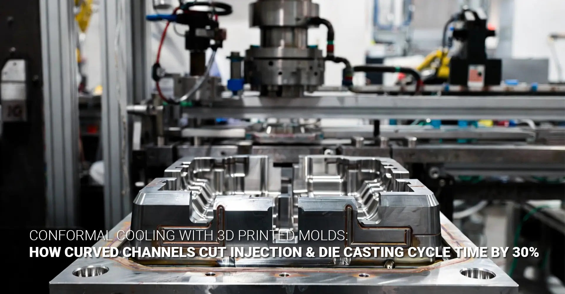
Conformal Cooling With 3D Printed Molds: Can Curved Channels Really Cut Your Injection & Die Casting Cycle Time by 30%?
If you run a high-volume injection molding or die casting operation, you already know the pressure. Faster cycles. Fewer defects. Longer tool life. But here's what most engineers miss — the biggest time thief in your process isn't injection speed or opening time. It's cooling.
Specifically, it's the way your cooling channels are designed. And right now, there's a good chance they're designed around what a drill bit can do — not what your part actually needs.

Here's the short answer if you're in a hurry:
Conformal cooling uses 3D-printed curved channels that follow the shape of your mold cavity. Because channels stay close to the cavity wall everywhere — including around cores, ribs, and thick sections — heat is removed faster and more evenly. The result: cooling time drops by 30–50%, total cycle time drops by 20–30%, and thermal fatigue cracking drops dramatically. For production molds running 10,000+ shots per year, the investment typically pays back in under six months.
That's the core answer. But if you want to understand why it works, how to evaluate it for your mold, and what the real numbers look like — keep reading.
Table of Contents
- Why Is Your Mold's Straight-Hole Cooling Wasting Up to 30% of Your Cycle Time?
- What Exactly Is Conformal Cooling, and How Do 3D Printed Channels Follow a Part's Contours?
- Where Does the 30% Cycle Time Reduction Actually Come From?
- Does Conformal Cooling Prevent Mold Cracking and Thermal Fatigue Too?
- Conclusion
Why Is Your Mold's Straight-Hole Cooling Wasting Up to 30% of Your Cycle Time?
Most mold engineers focus on injection pressure, gate location, and runner design. These matter — but they're not where most cycle time hides. The real culprit is the cooling phase. And in most production molds today, the cooling phase is being held hostage by a fundamental tool limitation: the drill bit goes straight.
Conventional mold cooling relies on drilled channels — straight bores machined through the mold block. This method has been standard for decades. It works. But it has one hard geometric limit that directly affects your industrial machinery output: drill bits cannot curve around features.
The key numbers you need to know:
| Phase | Share of Total Cycle Time |
|---|---|
| Injection | 10–20% |
| Packing / Holding | 10–15% |
| Cooling | 50–70% |
| Ejection / Mold Open | 5–10% |
Cooling is, by far, the longest phase. So when cooling is inefficient, every second of waste is multiplied across millions of shots.
Here's what happens with straight drilled channels in a complex mold:
- Cores, ribs, and thick bosses sit far from the nearest channel.
- These areas cool slowly — much slower than the rest of the cavity.
- The entire cycle must wait for the slowest-cooling spot before the part can be ejected.
- That one hot spot might add 8, 12, or even 20 extra seconds to every single cycle.
This is the geometry mismatch at the heart of conventional cooling. Injection mold cooling optimization has been limited not by engineering knowledge, but by manufacturing capability — until additive manufacturing changed the equation.
"You can add more straight channels, but you can't make them curve. That's the wall conventional machining hits."
The result of poor cooling channel placement isn't just a longer cycle. It also means uneven shrinkage across the part. One side cools faster than the other. The part warps. You get sink marks over thick sections. Secondary straightening or scrap follows. Each of these outcomes adds cost — and none of them would exist if the cooling were uniform from the start.
Understanding this problem is the first step. The second step is understanding what conformal cooling actually does to solve it.
What Exactly Is Conformal Cooling, and How Do 3D Printed Channels Follow a Part's Contours?
The term "conformal" simply means "following the shape of." A conformal cooling channel follows the shape of your mold cavity — staying at a consistent distance from the cavity wall as it curves, bends, and weaves around every feature of your part geometry.
This sounds simple. But it's only possible because of one manufacturing breakthrough: 3D printing for mold and die applications, specifically Direct Metal Laser Sintering (DMLS).
DMLS builds metal parts layer by layer from fine powder — fusing each layer with a high-powered laser. There is no drill bit. There is no cutting tool that has to travel in a straight line. The machine builds the part — including internal channels — in three dimensions, exactly as designed.
What this means in practical terms:
- Channels can curve around cores that a drill could never reach.
- Channels can spiral around cylindrical features for even coverage.
- Channels can branch and merge to balance flow and pressure.
- Most importantly, channels can maintain a constant 5–10mm distance from the cavity wall — everywhere, not just where a drill could get close.
Conformal cooling channel design gives engineers a completely new set of tools. Instead of asking "where can I fit a straight hole?", they ask "what cooling path would keep every square centimeter of this cavity surface at the same temperature?"
The channels are typically printed as smooth, round-bore tubes — not rough-cut drilled holes. This smooth interior surface also reduces flow turbulence and improves heat transfer coefficient. Clean, turbulent (but not chaotic) flow is ideal for pulling heat out of the mold wall.
What additively manufactured tooling enables that machining cannot:
| Feature | Conventional Drilled | DMLS Conformal |
|---|---|---|
| Channel path | Straight only | Any 3D curve |
| Proximity to cavity | Varies — often 20–40mm in complex areas | Consistent 5–10mm everywhere |
| Coverage around cores | Poor — dead zones | Complete |
| Surface finish inside channel | Rough (drill marks) | Smooth (sintered) |
| Design freedom | Low | High |
For die casting mold conformal cooling applications — where heat loads are extreme and tool life is critical — this design freedom is not a luxury. It's a competitive advantage that changes the ROI calculation entirely.
Where Does the 30% Cycle Time Reduction Actually Come From?
Let's get specific. The claim of 20–30% total cycle time reduction sounds compelling — but where does it actually come from? And is it realistic for your application?
The math is straightforward once you understand the baseline.
Step 1: Cooling is 50–70% of your cycle.
If your total cycle is 60 seconds, your cooling phase is likely 30–42 seconds.
Step 2: Conformal cooling cuts the cooling phase by 30–50%.
In well-designed applications, conformal channels reduce the cooling phase from 35 seconds to 18–24 seconds. That's because:
Heat is extracted faster — channels are closer to the hot surface everywhere.
No hot spots force the cycle to wait — the entire cavity reaches ejection temperature at the same time.
Mold temperature regulation becomes more precise — water flow can be tuned for each zone independently.
Step 3: Calculate the total cycle impact.
| Phase | Conventional | Conformal |
|---|---|---|
| Injection | 8 sec | 8 sec |
| Packing | 7 sec | 7 sec |
| Cooling | 35 sec | 20 sec |
| Ejection | 10 sec | 10 sec |
| Total | 60 sec | 45 sec |
That's a 25% reduction in total cycle time — just from changing the cooling channel geometry. No new injection machine. No faster robots. No process shortcuts.
The downstream benefits compound the savings:
- Less warpage → fewer parts rejected → lower scrap rate
- No secondary straightening → labor savings
- Consistent part dimensions → less inspection time
This is where the reduce cycle time 3D printed mold value proposition becomes undeniable at scale. If you run a mold for 500,000 shots per year at 60 seconds per cycle, that's 8,333 hours of press time annually. Drop the cycle to 45 seconds, and you reclaim 2,083 hours — or run the same number of parts in 6,250 hours instead.
Real-world example: Automotive housing die casting mold
A large automotive housing die casting mold — 850mm × 600mm tool face — was originally designed with conventional straight cooling:
- Conventional setup: 90-second cycle / 60-second cooling phase / visible hot spots at rib intersections / first cracking at 15,000 shots
- After conformal insert retrofit: 62-second cycle / 35-second cooling phase / uniform thermal map / no cracking observed at 40,000 shots
That's a 31% cycle time reduction and a tool life improvement of 2.7× — all from redesigning the cooling channel geometry using additively manufactured tooling.
For applications like kitchen appliances with complex aesthetic surfaces and thin-wall sections, uniform cooling also means better surface finish consistency — fewer sink marks, better gloss uniformity, less post-mold rework.
Does Conformal Cooling Prevent Mold Cracking and Thermal Fatigue Too?
Cycle time gets most of the attention. But for engineers managing large, expensive production molds, thermal fatigue mold cracking is often the more painful problem — and conformal cooling addresses it directly.
Thermal fatigue is what happens when a mold is repeatedly heated (by injected material) and cooled (by the cooling system) thousands of times. Each heating and cooling cycle causes the mold steel to expand and contract. If different areas of the mold heat and cool at different rates, internal stresses build up at the boundaries between hot and cool zones.
Over time, those stress concentrations produce microcracks. Microcracks grow into visible cracks. Visible cracks mean scrap, downtime, and eventually a scrapped mold that cost tens of thousands of dollars to build.
The root cause of thermal fatigue cracking is not temperature — it's temperature difference. Even high temperatures are tolerable if the mold heats and cools uniformly. The damage comes from gradients.
Why uniform cooling mold design prevents cracking:
- Conformal channels eliminate hot spots — the entire cavity surface reaches similar temperatures during each cycle.
- Lower temperature gradients mean lower thermal stress at every point in the mold.
- The mold expands and contracts more uniformly — stress concentrations never reach the threshold that initiates cracking.
The result: mold life increases dramatically. Tools that previously cracked at 15,000–20,000 shots routinely reach 40,000–60,000 shots with conformal cooling. For a mold that costs $80,000–$150,000 to build, doubling or tripling tool life is worth tens of thousands of dollars — independent of any cycle time benefit.
The surface finish connection
Thermal fatigue cracking doesn't just shorten mold life — it degrades part quality before the mold fails completely. Early-stage microcracks appear as texture inconsistencies, flow lines, or surface defects on the molded part. For any application requiring a premium surface finish — automotive trim, consumer electronics, medical device housings — this is unacceptable.
Maintaining uniform cooling preserves the cavity surface integrity for the full tool life. Parts produced at shot 40,000 look the same as parts produced at shot 1,000.
When does conformal cooling justify its cost for thermal fatigue prevention alone?
Ask these three questions:
- Does your current mold show hot spots in thermal imaging? (If yes, thermal fatigue is already accumulating.)
- Is your mold made from H13 or P20 steel with complex geometry? (Higher-complexity geometry = higher stress concentration risk.)
- What does one mold replacement cost — and how many do you replace per year?
If mold replacement is costing you more than $30,000 per year in a single production line, conformal cooling will likely pay for itself through tool life extension alone — before you count a single second of cycle time savings.
Productivity improvement tooling decisions like this are rarely just about speed. The most durable ROI case for conformal cooling combines faster cycles, fewer defects, and dramatically longer tool life into a single investment.
Conclusion
Let's bring this together clearly.
Conformal cooling with 3D-printed mold inserts delivers two distinct, measurable wins:
✅ Win 1: 20–30% shorter cycle time
- Cooling is 50–70% of your cycle.
- Conformal channels cut the cooling phase by 30–50%.
- Every second saved multiplies across hundreds of thousands of shots.
✅ Win 2: 2–3× longer mold life
- Uniform cooling eliminates temperature gradients.
- Lower thermal stress means no premature cracking.
- Tool replacement costs drop significantly.
The cost reality:
| Factor | Detail |
|---|---|
| Insert cost premium | 2–3× vs. conventional machined insert |
| Total mold cost increase | Typically 20–40% |
| Payback period (high-volume) | Often under 6 months |
| Minimum volume threshold | ~10,000–20,000 shots/year |
When to specify conformal cooling:
- ✅ Cooling is more than 40% of your current cycle time
- ✅ Your part has complex geometry (deep cores, thin ribs, thick bosses)
- ✅ You're seeing hot spots in thermal imaging
- ✅ Annual volume exceeds 20,000 shots
- ✅ Mold replacement costs are significant in your operation
- ❌ Low-volume prototype or short runs (straight channels are fine)
- ❌ Simple flat geometry with no difficult-to-reach features
Your practical next step:
Start with a thermal simulation of your current mold design. Identify where the hot spots are. Then bring those results to a 3D-printed mold specialist and ask for a conformal insert design covering those specific zones. You don't have to rebuild the entire mold — conformal inserts can often be retrofitted into an existing mold base at 30–50% of new mold cost.
In 2026, conformal cooling is no longer an experimental technology. It is a proven, production-ready solution for any high-volume mold where cooling is the bottleneck — and for most complex molds, it is.
📎 External Links & Further Reading
[3D printing for mold and die][^1]
[conformal cooling channel design][^2]
[additively manufactured tooling][^3]
[injection mold cooling optimization][^4]
[reduce cycle time 3D printed mold][^5]