Why Do Sharp Corners in Shaft Grooves Wreck Your CNC Turning Tools?
Why Do Sharp Corners in Shaft Grooves Wreck Your CNC Turning Tools?
If your production line keeps stopping for tool changes, the real problem might not be your machine or your operator. It could be hiding in your shaft drawing. Sharp corners at the bottom of relief grooves put enormous stress on cutting tools, and that stress adds up fast. Every chipped insert means downtime, wasted material, and a delayed shipment. The good news is that this problem has a simple fix. When you work with a shop that offers dependable CNC lathe machining services, a small change in groove geometry can save you thousands of dollars over a production run. This article walks through exactly why sharp corners cause so much damage, and what design changes actually solve the issue.

Quick Answer: A sharp 90-degree corner in a relief groove concentrates cutting force and heat into one tiny spot. That concentration causes chipping and fast tool wear. Adding a small radius, usually between 0.2mm and 0.5mm, spreads out the load. As a result, tools last much longer, and studies on cutting-edge geometry have shown tool life gains of over 30 percent from this change alone. When combined with proper groove width and insert selection, the total improvement can be even bigger.
So, why does something so small make such a big difference? Let's break it down step by step, starting with the actual mechanics of why sharp corners cause damage in the first place.
Table of Contents
- Why Do Sharp Corners Wreck Forming Tools During Shaft Turning?
- What Is a Relief Groove and Why Does DIN 509 Matter?
- How Does a Simple Radius Change Extend Turning Tool Life?
- Which Standard Grooving Insert Fits Your Shaft Design?
- Conclusion
Why Do Sharp Corners Wreck Forming Tools During Shaft Turning?
Picture squeezing a rubber ball with your whole hand versus poking it with one finger. The finger creates way more pressure in one small spot. That is exactly what happens when a cutting tool meets a sharp 90-degree corner. All the force lands in one tiny area instead of spreading out. Engineers call this a "stress riser." A stress riser is any sharp change in shape that pulls stress toward itself, almost like a magnet.
In short: sharp corners act like tiny stress magnets, and that stress leads to fast, expensive tool damage.
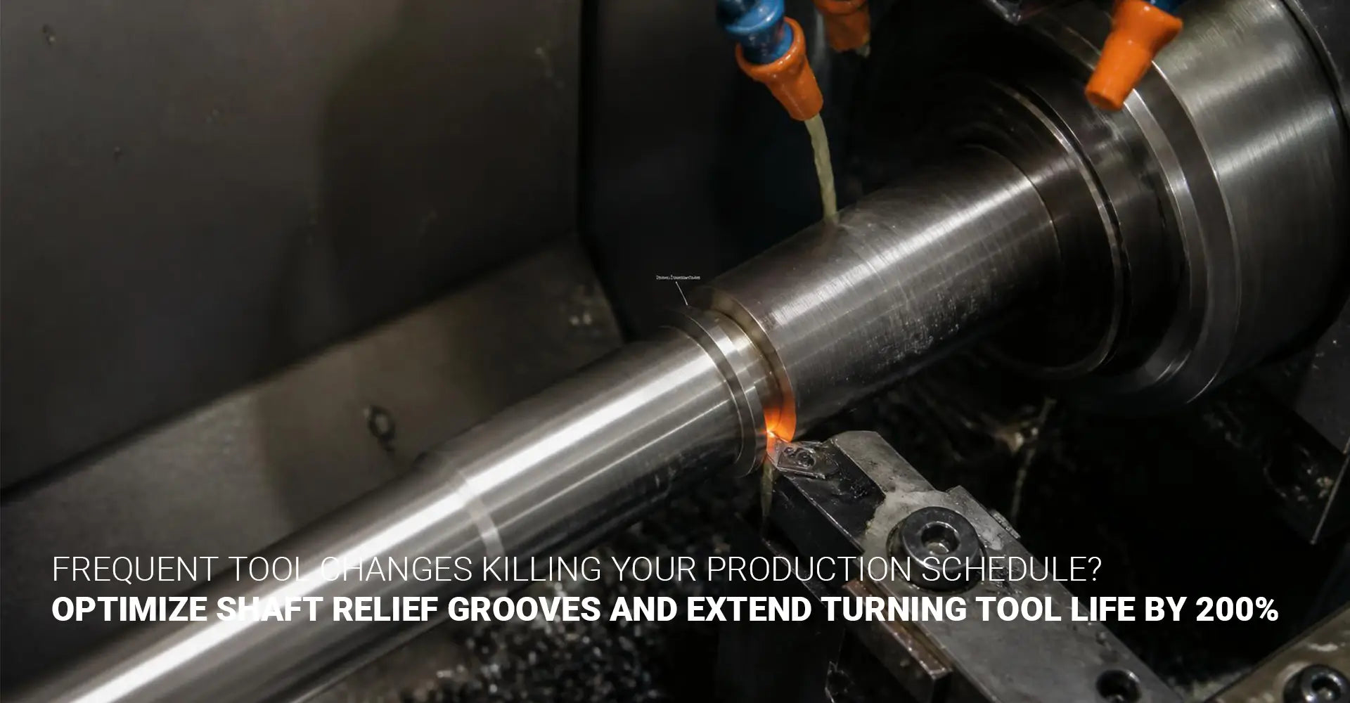
Here is where things get technical, but stick with us. When a forming tool cuts into a sharp corner, both heat and mechanical load pile up at that single point. Over time, this repeated stress causes tiny cracks to form at the tool's cutting edge. Those cracks grow with every pass, until a chip breaks off the insert. Once a chip appears, the tool can no longer cut cleanly, so it either needs to be replaced or reground. This is the core reason behind unwanted forming tool wear reduction failures on many production floors, and it is often traced right back to a groove drawing that never accounted for how cutting forces actually behave. If your parts include shafts, sleeves, or pins, checking your undercut geometry before it reaches the machine shop is one of the smartest things you can do for your budget.
What Is a Relief Groove and Why Does DIN 509 Matter?
A relief groove, sometimes called an undercut, is a small cut made into a shaft where two different surfaces meet. Think of the spot on a bolt where the smooth shaft transitions into the threads. That little groove gives space for a grinding wheel, an assembly part, or a thread-cutting tool to finish its job without hitting the wrong surface. Without it, tools would bump into unwanted material, and parts could end up damaged or out of spec.
In short: a relief groove creates clearance so grinding, assembly, or threading tools can do their job cleanly.
Now, here is why standards matter so much in this process. Engineers rarely design a groove from scratch every single time. Instead, they reference an established system that defines groove shapes, depths, and widths. This is where the DIN 509 undercut standard comes in. DIN 509 lays out four official undercut forms, labeled E, F, G, and H, each built for a different purpose. Form F, for example, has a flat bottom with built-in radii to spread out stress at shaft shoulders. Form G includes a curved bottom for precision grinding clearance. Typical radii range from about 0.25mm for standard turning up to nearly 0.90mm for grinding relief work. When your drawing simply calls out "Undercut per DIN 509-E," your supplier instantly knows the exact shape and dimensions to cut, with no guesswork involved. That clarity alone helps avoid slow email chains, mistakes, and shaft groove design changes made after the tooling is already built.
How Does a Simple Radius Change Extend Turning Tool Life?
So, we know sharp corners cause damage. What actually fixes it? The answer is surprisingly simple: add a radius. A radius is just a small curve instead of a hard, sharp angle. Instead of two flat surfaces meeting at a point, the transition becomes smooth and rounded.
In short: swapping a sharp corner for a small radius spreads out cutting force, and that alone can add serious life to your tooling.
Why does this small curve matter so much? Because of how physics handles force. A sharp corner pushes all the cutting pressure into a single point, like we discussed earlier. A rounded edge, on the other hand, spreads that same pressure across a wider area. Less pressure in any one spot means less heat, less friction, and less wear on the cutting edge. This process, sometimes called radius transition turning, is one of the most cost-effective upgrades a shaft design can receive. Suppliers who understand insert corner radius selection will typically recommend a radius between 0.2mm and 0.5mm for most industrial shaft applications. That range is small enough to keep tight tolerances intact, yet large enough to meaningfully cut down on tool stress. Better yet, this change usually does not slow down your cycle time. In fact, because a radiused groove can often be cut in a single pass with a standard insert, some shops actually see faster overall production once the design shifts away from sharp corners.
Which Standard Grooving Insert Fits Your Shaft Design?
Here is a mistake that happens more often than you would think. A designer draws a groove that is narrower than any standard tool on the market. Maybe it looks fine on paper, but once it reaches the machine shop, the team has to grind a custom tool just to cut that one feature. Custom tools cost more, take longer to source, and often are not as strong as standard ones.
In short: matching your groove width to a standard grooving insert keeps costs down and keeps your tooling strong.
Let's dig into the numbers. Most standard grooving inserts are built for a minimum width of about 1.2mm. If your groove is narrower than that, your supplier is stuck choosing between a custom-ground tool or a specialty insert, and both options usually cost more per part. Designing with this minimum in mind means your machinist can pull an off-the-shelf tool straight from the tray, already backed by a proven chipbreaker shape and a reliable clamping system. This single decision supports real tool life extension CNC turning results, because standard inserts are engineered and tested for exactly this kind of repeated work. It also plays into something called CNC turning DFM, which stands for Design for Manufacturability. DFM simply means designing a part with the actual manufacturing process in mind, rather than designing it in isolation and hoping it works out. A part built around DFM principles almost always costs less to produce and ships faster.
If your production involves complex multi-surface parts, not just shafts, it is worth checking with a shop that also handles broader work like custom CNC milling services, since many of these same DFM principles apply across machining processes, not just turning. And because material choice affects how much a radius helps, it is smart to loop in a supplier who works across different CNC metals and plastics so your groove design gets matched to how your specific material actually behaves under stress.
Before your next print goes out for quotes, run through this quick checklist:
- Is every relief groove specified with a radius of at least 0.2mm?
- Does the groove width match a standard insert size, ideally 1.2mm or wider?
- Does the drawing reference DIN 509, or an equivalent standard, instead of leaving the shape open to interpretation?
- Has your supplier been asked what corner radius they recommend for this specific material?
- Have you asked to see a tool life comparison between a sharp and radiused version of a similar part?
A supplier who can answer these questions with real data, not guesses, is a supplier who understands relief groove optimization at a practical level. That kind of partner protects your budget long before the first part is ever cut.
Conclusion
Small design choices carry a big impact once parts move into full production. A sharp corner might look harmless on a drawing, but on the shop floor, it quietly drains your tooling budget one chipped insert at a time. By adding a proper radius, sizing your grooves to match standard inserts, and referencing recognized standards like DIN 509, you set your shaft up for smoother machining and far fewer surprises. These changes cost nothing extra at the design stage, yet they pay off every single day your parts run through production.
If you are sourcing turned shafts, sleeves, or any rotational part, it pays to work with a manufacturer who treats groove design as part of the engineering conversation, not an afterthought. A team experienced in CNC machining services can flag these issues before cutting ever begins, saving you both time and money. And for buyers managing larger equipment programs, a supplier familiar with full industrial machinery components can help make sure every part, not just the shafts, is designed with long-term durability in mind.
Recommended External Reading:
[CNC lathe machining services][^1]
[relief groove optimization][^3]
[tool life extension CNC turning][^4]
[^1]: Freeway Corporation (USA) – a precision turned components manufacturer with over 30 multi-spindle screw machines and multiple CNC turning centers handling up to 2 7/8" bar stock and 7" chucking blanks, offering secondary operations including broaching, thread rolling, centerless grinding, tapping, and milling[reference:0][reference:1].
[^2]: Anebon (USA-facing) – a detailed engineering guide on managing undercut dimensions in precision shaft grooves, covering tool deflection (3mm grooving insert at 25mm overhang bends 5–8 μm under normal cutting forces), insert selection, coolant delivery, and tool-path strategies for holding IT6/IT7 tolerances on materials including 4140, 17-4PH, Inconel 718, and Ti-6Al-4V[reference:6][reference:7].
[^3]: A grooving basics Q&A from MSC Industrial Supply (US-based industrial distributor) featuring Walter Tools expertise, explaining that selecting the toolholder with the shortest cutting depth provides the best rigidity and extends insert tool life, and recommending the widest insert possible for maximum strength and heat dissipation[reference:1][reference:2].
[^4]: A 2025 article from IPE Magazine (UK-based engineering publication) covering Walter's Groov·tec™ GD5011-P grooving system with a patented double-serration profile that provides positive-locking stability, extends service life of tool support by up to 50%, and delivers 30 to 150% longer tool life than standard prismatic clamping systems[reference:6][reference:7][reference:8].
[^5]: A case study from Dieterle (Germany) detailing the use of custom profiled grooving inserts to machine an O-ring groove with a 55° undercut in stainless steel (1.4305) on an INDEX C200 CNC lathe[reference:0][reference:1]. The ANF system's face grooving tools provide stable radial cutting and good chip control for demanding undercut geometries[reference:2].